
Manual Adjustable LED Driver

The AD5228 is a dual-channel, digitally controlled potentiometer (DCP) that can be employed in applications requiring precise control over electrical signals. It features a 256-position wiper setting, allowing for fine-tuning of output levels, which is particularly useful in LED driver circuits for backlighting applications. The device operates via a simple two-wire interface, enabling easy integration with microcontrollers or other digital systems.
In a typical application, the AD5228 can be configured to adjust the brightness of an LED by varying the resistance in the circuit. The LED driver circuit can consist of a power supply, the AD5228, and the LED itself. The output from the AD5228 is connected to the LED, controlling the current flowing through it based on the wiper position selected via the digital interface. This configuration allows for smooth dimming capabilities and precise control over the LED brightness, which is essential for enhancing user experience in LCD displays.
Additionally, the AD5228 supports both linear and logarithmic taper options, providing flexibility in response characteristics based on application needs. The device also has built-in EEPROM functionality, allowing for the storage of settings and configurations, which can be particularly beneficial in applications where consistent performance is required after power cycling.
To implement the AD5228 effectively in an LED driver circuit, careful consideration must be given to the power ratings, the maximum allowable current through the LED, and the overall thermal management of the circuit to prevent overheating. Proper layout practices, including adequate grounding and minimizing parasitic capacitance, will enhance the performance and reliability of the circuit.In many electronics-level adjustments such as LED drivers for LCD panel backlight controls, we can use AD5228. A manually adjustable LED driver is shown on.. 🔗 External reference
Related Circuits
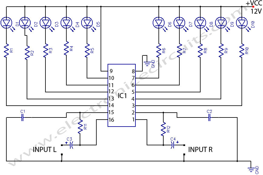
LED stereo sound level indicator for audio amplifier. Many circuits can be designed as level indicators by using a comparator IC or transistors, but... The LED stereo sound level indicator serves as a visual representation of the audio signal levels...
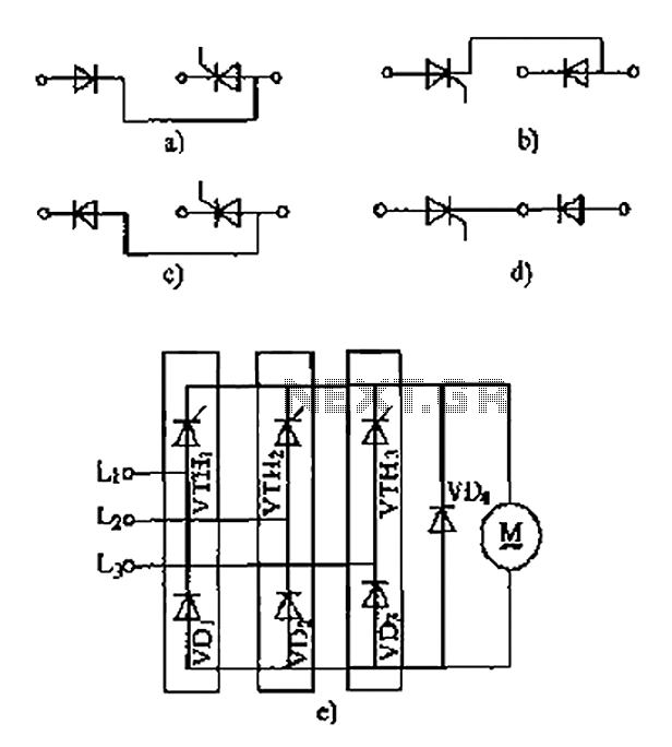
The thyristor linking arm rectifier module is a three-phase half-controlled bridge rectifier circuit. The thyristor-rectifier module linking arm consists of a thyristor and a rectifier diode connected in series or parallel, designed to fulfill specific requirements in power circuits....
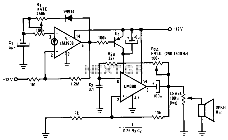
The LM380 functions as an astable oscillator, with the frequency set by R2 and C2. By adding Q1 and driving its base, the output of an LM3900 is configured as a second astable oscillator. This setup gates the output...
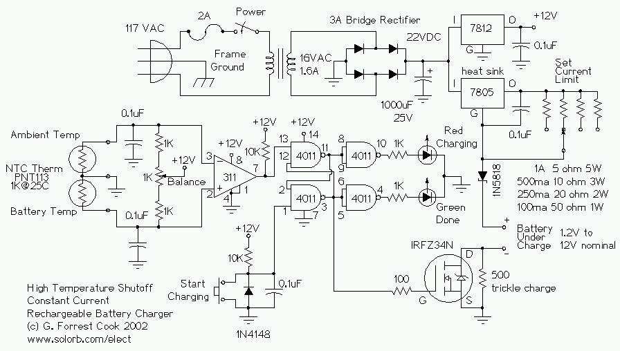
This circuit is designed for a temperature-controlled constant current battery charger, compatible with NiCd, NiMH, and other rechargeable cells. It operates on the principle that most rechargeable batteries exhibit an increase in temperature when they are fully charged. Overcharging...
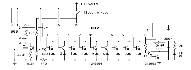
This circuit provides a visual 9-second delay using 10 LEDs before closing a 12-volt relay. When the reset switch is closed, the 4017 decade counter is reset to the 0 count, illuminating the LED driven from pin 3. The...
The construction LED circuit illustrated in the figure requires manual power. Once powered, the light will blink to alert individuals to pay attention to safety. The circuit is designed to enhance safety awareness in construction environments by utilizing a blinking...