
LED STEREO SOUND LEVEL INDICATOR

The LED stereo sound level indicator serves as a visual representation of the audio signal levels in an amplifier circuit. This circuit typically employs a comparator integrated circuit (IC) or discrete transistors to detect and indicate the amplitude of the incoming audio signal.
In a basic configuration, the audio signal is fed into the circuit, where it is compared to a reference voltage. The comparator IC evaluates the input signal levels and drives the LED indicators accordingly. When the audio signal exceeds the predetermined threshold, the comparator outputs a high signal, illuminating the corresponding LEDs. This allows users to visually monitor the audio levels, ensuring that they do not exceed optimal limits, which could lead to distortion or damage to the audio equipment.
The design can include multiple LEDs arranged in a bar graph format, providing a more detailed indication of the sound level. Each LED corresponds to a specific range of audio levels, enabling users to gauge the overall sound dynamics effectively. Additionally, the circuit can be enhanced with features such as adjustable sensitivity and hysteresis to prevent flickering of the LEDs during rapid changes in audio levels.
Power supply considerations are also essential in the design of the LED sound level indicator. The circuit typically operates on a low-voltage supply, commonly between 5V to 12V, ensuring compatibility with standard audio equipment. Proper biasing of the comparator and current-limiting resistors for the LEDs must be calculated to ensure reliable operation and longevity of the components.
Overall, the LED stereo sound level indicator is a valuable tool in audio applications, providing an intuitive and immediate visual representation of sound levels, which is crucial for both performance and equipment protection.LED STEREO SOUND LEVEL INDICATOR FOR AUDIO AMPLIFIER // Many circuits can be designed as level indicators by using a comparator IC or transistors but.. 🔗 External reference
Related Circuits
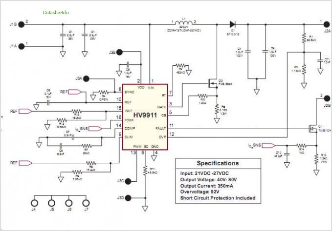
Conventionally, a MOSFET with a voltage rating of 1500V or a Half-Bridge configuration utilizing two MOSFETs rated at 800-900V is employed for Switch Mode Power Supply (SMPS) applications that require input voltages exceeding 380Vac. However, these methods present challenges,...
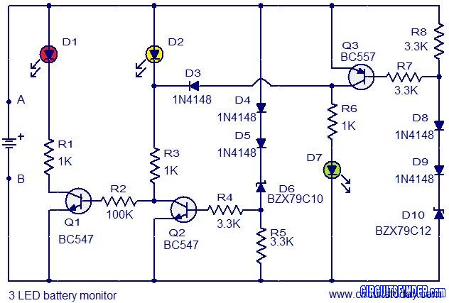
This is the circuit diagram of a 3 LED bar graph type battery monitor circuit that is ideal for monitoring the voltage level of an automobile battery. When battery voltage is 11.5V or less, transistor Q1 will be on...
This is a very simple circuit that can be used to test whether a pot is dry or not. When the two probes are inserted in wet soil, then the resistance between the sensors are low. The base of...
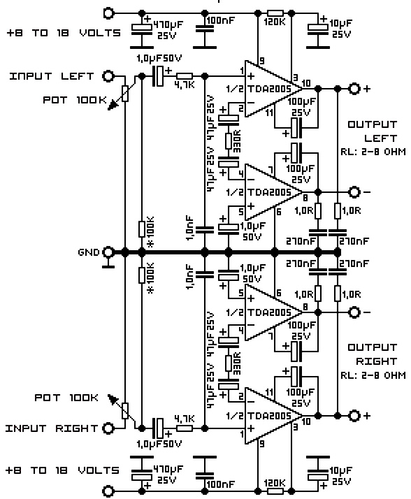
A 20W TDA2005 stereo amplifier designed for various applications, including the amplification of medium power speakers. It is suitable for automotive use; however, the power supply must be equipped with a choke of at least 150mH and should provide...
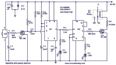
555 Timer TV Remote Controlled Home Appliance Circuit Diagram. Features: 555 timer IC to avoid fast switching. You can only switch the circuit. The 555 timer integrated circuit (IC) is a versatile component widely used in various electronic applications, including...
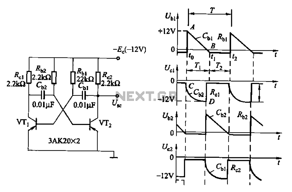
Also known as a no-shot multivibrator, this circuit is often utilized as a pulse (square wave) signal source. The astable flip-flop functions as a strong positive feedback amplifier, with its two branches coupled by an RC timing circuit, resulting...