
marker generator

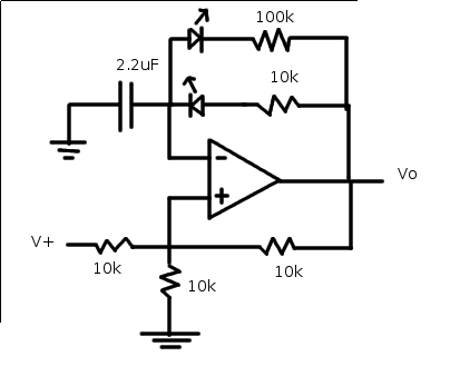
The circuit described involves a fundamental oscillator configuration utilizing a 4060 integrated circuit, which is known for its frequency division capabilities and oscillator functionality. The inclusion of a 100K Ohm resistor between pins 10 and 11 plays a crucial role in setting the timing characteristics of the oscillator, influencing the frequency stability and output waveform shape. The second resistor of 2K Ohm may be part of a feedback or biasing network, ensuring proper operation of the oscillator.
The capacitor values specified are critical for tuning the oscillator to the desired frequency. The fixed capacitor, approximately 39pF, and the variable capacitor, which can be adjusted between 39pF and 59pF, allow for fine-tuning of the oscillator's frequency. This tuning is essential for achieving the precise frequency required for the application, as indicated by the 4060 datasheet.
The output stage of the circuit, while not tested, is expected to exhibit interesting characteristics due to the diode's rapid conduction during the square wave's falling edge. This behavior may lead to the generation of harmonics, particularly at 10kHz, which are typically associated with non-linear switching elements in a circuit. The expectation of pronounced peaks in the output waveform suggests that the circuit may be designed for applications requiring sharp transitions and fast rise and fall times, which are beneficial in digital signal processing and pulse generation.
The planned verification with an oscilloscope will provide essential insights into the actual performance of the circuit, allowing for the observation of the output waveform and the presence of harmonics, thus confirming the theoretical expectations outlined in the circuit design.Resistor between pin 10 and 11 is a 100K Ohm one, the other a 2K. Fixed capacitor was by trial and error, to get crystal on the exact frequency, somewhere near 39pF and the variable one a little more: 39+20var, see 4060 datasheet. The output circuit on the above image wasn`t tested (just normal cap coupling was) but I`m sure it will give nice peaks because diode will conduct very shortly on the down flank of the square wave,
generating lot`s of 10Khz harmonics and more than the simple square wave. I need a scope to verify that. maybe next year. 🔗 External reference
Related Circuits
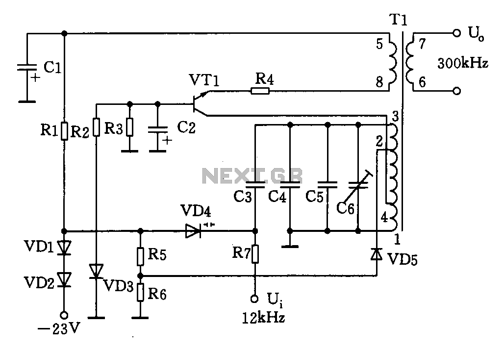
This circuit is designed for a 300 kHz signal generator. It includes components such as VT1, T1, VD4, and other associated elements. The voltage-controlled oscillator (VCO) employs an LC-tuned collector, with VT1 functioning as the oscillating transistor, varactor diode...
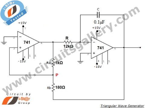
An operational amplifier-based triangular waveform generator is a simple circuit that is widely used in function generators. This circuit utilizes the 741 operational amplifier to create a triangular wave generator. The output waveform of an integrator will be triangular...
The process of converting a triangle wave waveform into a sine wave involves the adjustment of its transfer function using resistors R32 and R33. Modifying these resistors affects the linearity of the response. The differential output current from the...
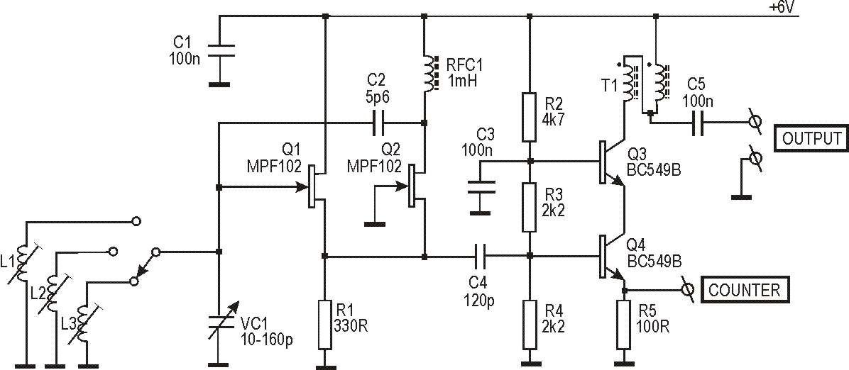
This circuit originated from work on two antenna analyzers, which are detailed elsewhere on this site. Both instruments incorporate an RF signal generator that serves as the signal source for driving the impedance bridge and detectors used to measure...
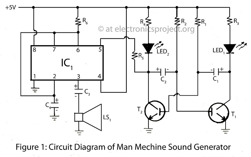
The Man Machine Sound Generator is a unique project within a series of alarm circuit diagrams, featuring descriptions of various types of alarm projects. The Man Machine Sound Generator is an innovative electronic circuit designed to produce sound signals in...
The relaxation oscillator generates a relatively consistent square wave. By altering the duty cycle, the effect can be visualized using LEDs. The following variation of the relaxation oscillator circuit can be assembled. The relaxation oscillator circuit typically consists of a...