
pulse generator circuit

The relaxation oscillator circuit typically consists of a resistor, capacitor, and a transistor or operational amplifier configured to produce a square wave output. In this variation, the duty cycle can be modified by adjusting the resistance and capacitance values, which influences the charging and discharging time of the capacitor.
To visualize the changes in duty cycle, LEDs can be incorporated into the circuit. When the output switches states, the LEDs will illuminate, providing a clear indication of the oscillation frequency and duty cycle. The circuit can be designed using a 555 timer IC in astable mode, where the duty cycle is determined by the ratio of the resistances and capacitance used in the timing configuration.
By selecting different resistor values (R1 and R2) and a capacitor (C1), the frequency and duty cycle can be manipulated. The duty cycle can be calculated using the formula:
Duty Cycle (%) = (R1 + R2) / (R1 + 2R2) * 100
This allows for precise control over the output waveform characteristics. The circuit should be powered by a suitable DC voltage source, and the output can be taken from the discharge pin of the 555 timer.
The schematic should indicate the connections for the resistors, capacitor, and the LED, ensuring that the LED is placed in series with a current-limiting resistor to prevent excessive current flow. By observing the LED's brightness and on/off timing, the effects of varying the duty cycle can be effectively demonstrated.With the relaxation oscillator, we basically achieved a fairly regular square wave. Let's change the duty cycle (and visualize the effect with LEDs). Wire up the following variation on the relaxation oscillator circuit 🔗 External reference
Related Circuits
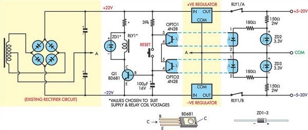
This circuit was designed to protect a dual rail power supply from shorts across the two rails. It uses an optocoupler to monitor each supply rail, with the internal LEDs powered from ZD2 and ZD3 and the associated resistors....
The volt-ampere characteristics of a tunnel diode exhibit an S-shaped curve. The peak current point, referred to as point P, represents the maximum current, while the valley point, denoted as point V, indicates the minimum current. Key parameters of...
The circuit below illustrates powering one or two LEDs from the 120-volt AC line using a capacitor to drop the voltage and a small resistor to limit the inrush current. Since the capacitor must pass current in both directions,...
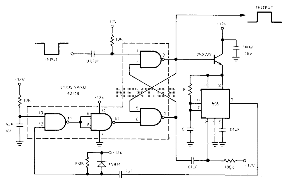
The 555 Timer facilitates a low-loss single-shot circuit and interfaces with the CMOS4011B NAND gate circuit. The standby power consumption is less than 50 µA. When the one-shot circuit is activated, the current consumption is 4.5 mA, and the...
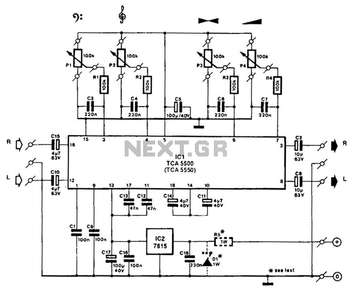
A Motorola TCA5500 or TCA5550 can be utilized to create a stereo preamplifier system equipped with tone controls. This circuit is designed to offer a gain of approximately 10 times, a tone-control range of 14 dB, and a volume...
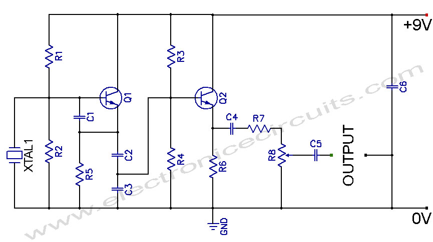
Crystal Controlled Oscillator Circuit. This general-purpose signal source is highly effective in signal-tracing applications. The output level is adjustable. The crystal-controlled oscillator circuit is designed to provide a stable and precise frequency output, which is essential for various electronic applications,...