
matrix keypad interfacing with spartan 3 primer

The matrix keypad operates on a grid structure, comprising 4 rows and 4 columns, which allows for efficient input detection. When a button is pressed, it connects a specific row to a specific column, creating a unique circuit that can be detected by the microcontroller. This method reduces the number of I/O pins required, as multiple keys can share connections, thereby optimizing the design for embedded systems.
In the context of the Spartan-3 Primer board, the keypad's I/O pins are configured to read the state of each button press. The rows are typically driven high, while the columns are monitored for any changes in state. When a key is pressed, the corresponding row and column will register a low signal, indicating the specific key that has been activated. This information can then be processed by the microcontroller to execute the desired function.
For implementation, it is essential to configure the microcontroller's GPIO (General Purpose Input/Output) pins correctly. Each row pin should be set as an output, while each column pin should be set as an input with pull-up resistors enabled. This setup ensures that the system can accurately detect button presses without floating inputs causing erroneous readings.
Additionally, debouncing techniques may be employed in the software to ensure that a single press does not register multiple times due to mechanical bounce, which is common in physical switches. This can be achieved through software delays or state change detection algorithms.
Overall, the integration of a 4x4 matrix keypad into embedded systems like the Spartan-3 Primer board enhances user interaction by providing a compact and efficient means for input, making it a valuable component in various applications.Matrix keypad consists of a set of buttons similar to an alphanumeric keyboard provided with keys usually marked with letters or numbers and various extra keys. Embedded systems which require user interaction must be interfaced with devices that accept user input such as a keypad.
The Spartan-3 Primer board has 4x4 Matrix Keypad, indicated as in Figure. Keypads arranged by matrix format, each row and column section pulled by high, all row lines and column lines connected directly by the i/o pins. 🔗 External reference
Related Circuits

This section of the I2C interfacing project focuses on constructing an acceleration sensor while also addressing two additional aspects: the advanced application of the PCF8591 chip (previously discussed in the context of the pressure sensor) and operating the bus...

This simple circuit is the electronic version of the combination lock. Using the special purpose LS7220 digital lock IC, the circuit allows a 4 digit combination of your choice to activate a relay for a set period of time....
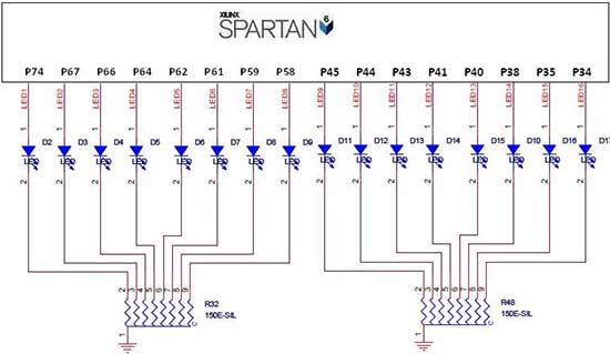
The Spartan-6 board features 16 LEDs connected to FPGA I/O pins, as detailed in the table below. The cathode of each LED is connected to ground through a 330-ohm resistor. To illuminate a specific LED, the corresponding FPGA control...
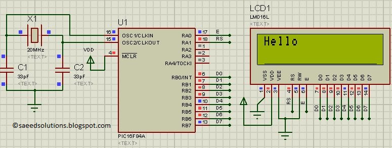
This post presents the LCD interfacing code utilizing the PIC16F84A microcontroller. The code is developed in the C programming language using MPLAB with the HI-TECH C compiler. The interfacing of an LCD (Liquid Crystal Display) with the PIC16F84A microcontroller...
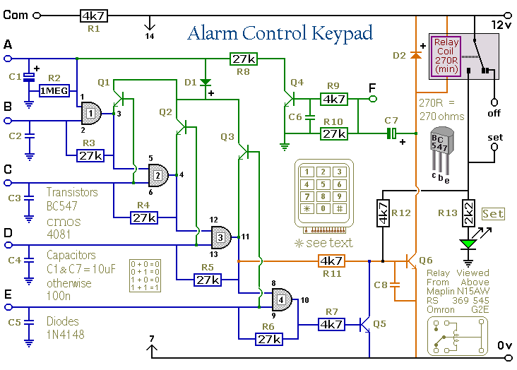
This keypad is designed for use with the Modular Burglar Alarm system, although it can be applied in various other contexts. Inputting the first four digits of a selected five-digit code will activate the relay, while entering the complete...
Analog to Digital Converter (ADC) interfacing with microcontrollers such as AVR, 8051, and PIC, including Digital-Ramp ADC, Successive Approximation ADC, Flash ADC, and basic working of an analog to digital converter. Analog to Digital Converters (ADCs) are essential components in...