
Maximum Load Capacitor that LMV116 can drive

The LMV116 operational amplifier is designed to provide an enhanced slew rate compared to its predecessor, the LMH6645. This characteristic makes it particularly suitable for applications requiring rapid signal processing. However, it is essential to note that the high-speed performance of LMH devices renders them sensitive to output capacitance. Typically, these devices are optimized for driving back-terminated loads, which means they are intended to operate with specific load conditions that minimize the risk of oscillation.
When subjected to direct capacitive loads, the LMV116 can exhibit oscillatory behavior at capacitance levels as low as 50 pF. To mitigate this issue, a common practice involves placing a resistor in series with the load capacitors. While this approach can effectively suppress unwanted oscillations, it may also inadvertently dampen desirable LC oscillations, which can be critical in specific applications, such as RF or high-speed digital circuits.
For designers and engineers utilizing the LMV116, it is crucial to consider the load characteristics and the potential impact of added series resistance on overall circuit performance. The operational amplifier's specifications should be carefully reviewed to ensure compatibility with the intended application. Additionally, users should be aware of the legal disclaimers associated with the use of materials and content provided by TI, which emphasize the importance of understanding the limitations and requirements for licensing when implementing these components in designs.
Overall, the LMV116 offers a valuable solution for applications demanding high-speed operation, provided that its sensitivity to output capacitance is appropriately managed within the design framework.The LMV116 is an enhanced slew rate version of the LMH6645. The high speed LMH devices are very sensitive to output capacitance (normally they drive back-terminated loads) and normally start oscillating with direct capacitive loads as low as 50pF. I just tested it out again placing a resistor in series with the load capacitors and it squelch the oscillations. But it also squelch the LC oscillations that I want. All content and materials on this site are provided "as is". TI and its respective suppliers and providers of content make no representations about the suitability of these materials for any purpose and disclaim all warranties and conditions with regard to these materials, including but not limited to all implied warranties and conditions of merchantability, fitness for a particular purpose, title and non-infringement of any third party intellectual property right. TI and its respective suppliers and providers of content make no representations about the suitability of these materials for any purpose and disclaim all warranties and conditions with respect to these materials.
No license, either express or implied, by estoppel or otherwise, is granted by TI. Use of the information on this site may require a license from a third party, or a license from TI. Content on this site may contain or be subject to specific guidelines or limitations on use. All postings and use of the content on this site are subject to the Terms of Use of the site; third parties using this content agree to abide by any limitations or guidelines and to comply with the Terms of Use of this site. TI, its suppliers and providers of content reserve the right to make corrections, deletions, modifications, enhancements, improvements and other changes to the content and materials, its products, programs and services at any time or to move or discontinue any content, products, programs, or services without notice.
🔗 External reference
Related Circuits

This circuit utilizes a 4049 integrated circuit (IC) to control a 2N2222 switching transistor. The transistor, in turn, drives a piezo transducer known as crystal 1. The circuit design begins with the 4049 IC, which is a hex inverter capable...
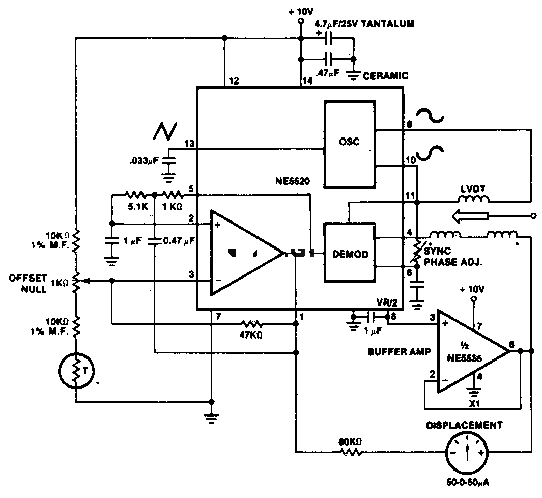
A simple motion transducer can be constructed using the provided circuit. The output is biased to one-half of the supply voltage, necessitating special interface circuitry for signal readout. One straightforward method involves utilizing a zero-center meter in a bridge...
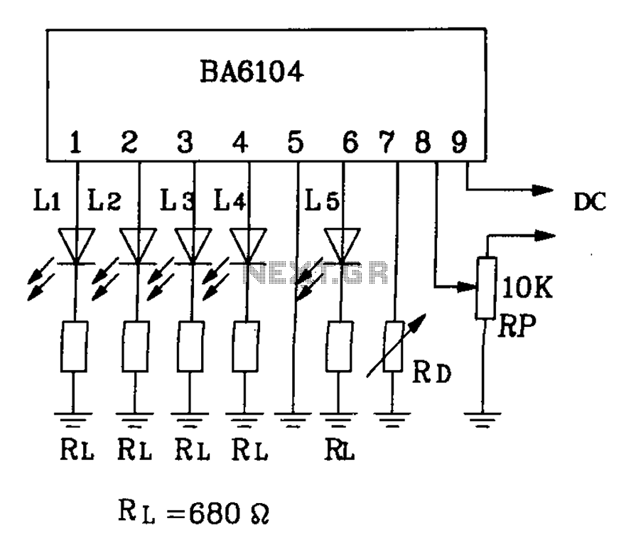
BA6104 is a five-digit LED level meter driver integrated circuit (IC) that features a basic application circuit. The input stage employs a PNP transistor with a composite base input, resulting in high input impedance. The output stage is configured...
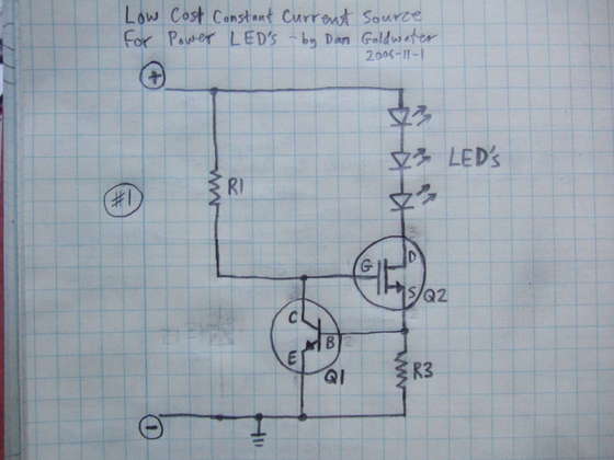
Here is a simple and cost-effective Power LED driver circuit. This power LED driver circuit is designed to efficiently drive high-power LEDs with a stable output. The circuit typically consists of a few key components: a power supply, a current...
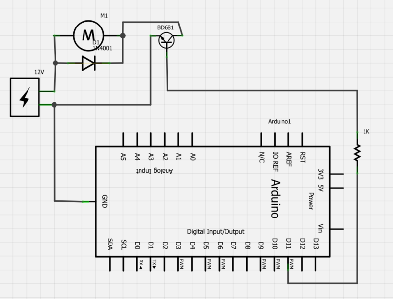
Power a 12V fan using a Darlington transistor to control the speed from an Arduino. When wired as described, nothing happens even though a PWM signal is being sent. It is suggested to edit the question and ensure the...
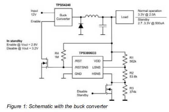
Small additional circuitry during standby can significantly enhance efficiency. In a modern vehicle, multiple microcontrollers are required to support safety, navigation, entertainment, and comfort electronics. The integration of additional circuitry during standby mode in automotive applications is crucial for optimizing...