ME218A: Soccer Pinball actuators
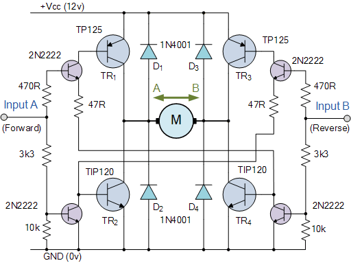
Due to power limitations, the design options for the flippers were constrained. Typically, pinball machines utilize linear solenoids, which at 12 V and 3 A offer inadequate performance. Conversely, employing DC, servo, or stepper motors posed challenges. To achieve sufficient speed, power, and mechanical durability, linear door-lock motors were selected to push and pull off-axis from the flipper pivot. The flipper design provides just enough speed and strength for a well-timed swing; therefore, rather than relying on return springs, each flipper motor operates in a push-pull configuration using a bidirectional H-bridge. The motor runs at full voltage for a predetermined duration in each direction, based on the minimum complete travel time. To avoid blocking code, timers in the TMRS12 module are utilized. Each flipper is constructed from a piece of ½" foam core sandwiched between two identical laser-cut acrylic pieces, secured with hot glue. The main pivot is made from a bolt with a smooth shaft section, fixed to the playing surface between nuts and metal washers. Nylon washers prevent the acrylic from binding to the components on the bolt. Although a true shoulder screw would have better controlled the tolerance stack, this design sufficed for the intended purpose. To ensure the playing surface is removable for easier construction and debugging while controlling the tolerances of the flipper-motor assembly, the motors are mounted directly to the underside of the playing surface, with features for the motors cut in the same process as the flippers. The layout of the playing surface and flipper mounting holes is clearly defined. To create a realistic arcade pinball experience, arcade buttons were purchased to maintain the true electromechanical operation expected in pinball games. The design includes a moving goalie that travels across the front of the goal, enhancing gameplay. A free printer was repurposed to provide a robust linear actuation platform with the appropriate size, speed, and power for the project. After isolating the cartridge position drive train and motor from the rest of the system, a removable goalie was attached for personalization. This removability allowed for secure mounting of the heavy drive train to the frame while maintaining a modular playing field. A PVC pipe serves as a low-friction support behind the goalie, preventing stress on the drive train from ball strikes. Similar to the flipper motors, the goalie motor is connected to a bidirectional H-bridge circuit, with the enable voltage sourced from the PWM channel of the C32. At the start of the game, the duty cycle is adjusted based on the difficulty level potentiometer, thus defining the game's difficulty by the speed of the goalie. The goalie’s position is communicated to the C32 via limit switches located at either end of the travel. When a limit switch is activated, the controller reverses the goalie direction in software. An additional direction change switch was added in parallel with the limit switches to enable single- or multi-player gameplay without modifying the existing hardware or software. This user-goalie feature enhances interaction but also increases the game's difficulty. During demonstrations, a notable collection of pennies was gathered, with soccer-themed stickers dispensed as prizes.
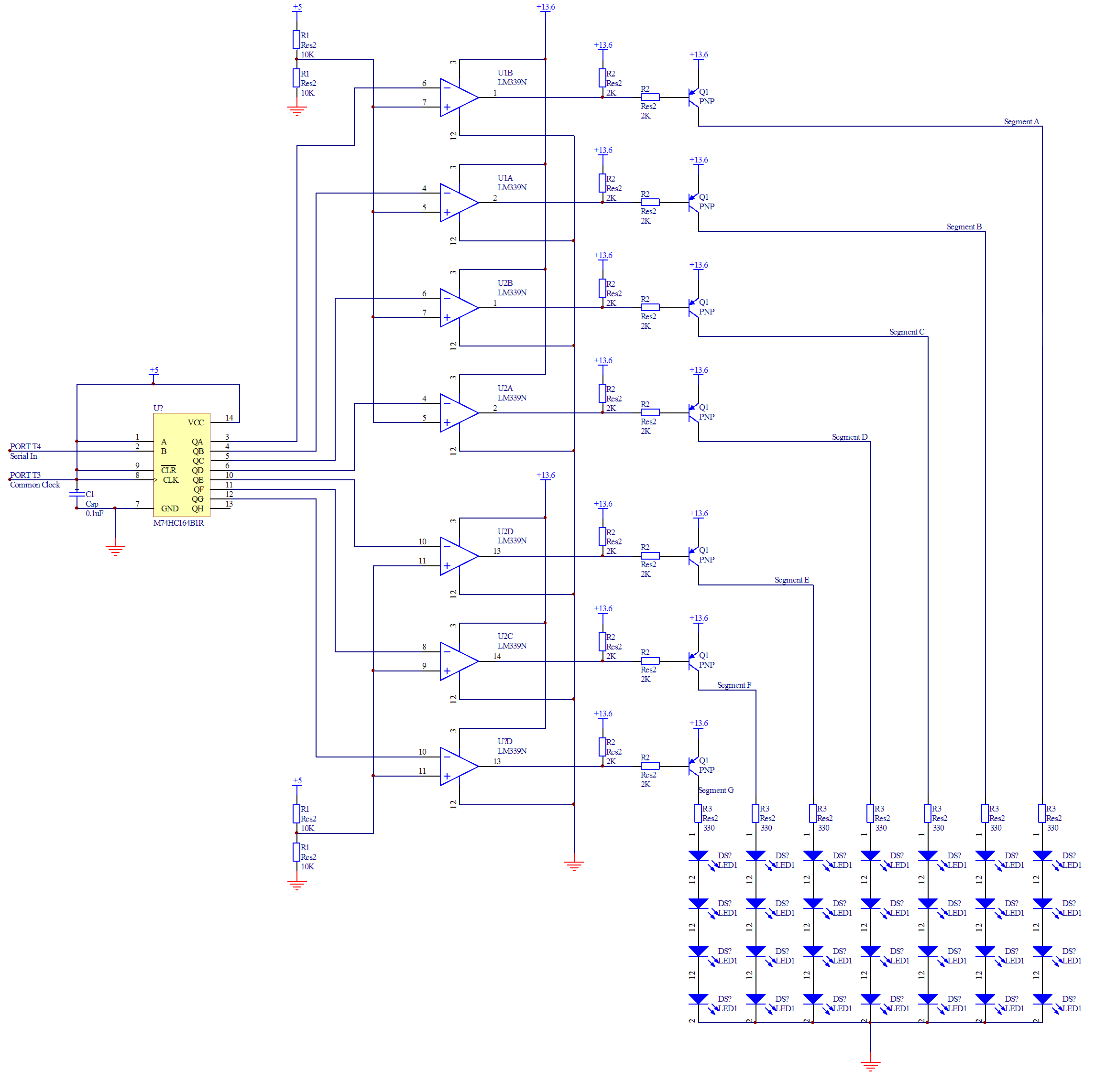
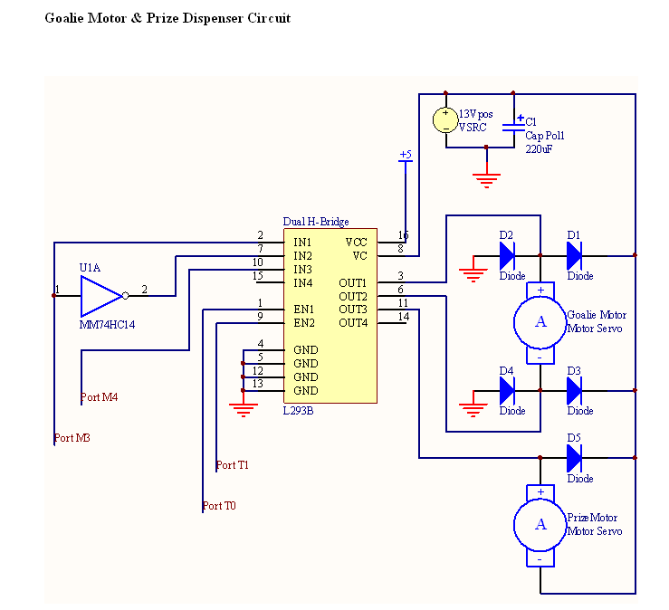
The electronic schematic for this pinball machine design involves several key components to ensure reliable operation. The linear door-lock motors, chosen for their robustness, are controlled via a bidirectional H-bridge circuit. This allows for precise control of the motor direction and speed, enabling the flippers to operate effectively. The H-bridge is interfaced with a microcontroller (C32) that manages the timing and control logic, ensuring that each motor receives the correct voltage and duration of operation.
Timers within the TMRS12 module are programmed to manage the motor activation times, preventing any blocking code that could interfere with gameplay. The flippers are mechanically mounted to the playing surface, with the motor assembly directly beneath, allowing for a compact and efficient design. The use of nylon washers is critical in reducing friction at the pivot point, ensuring smooth operation.
The moving goalie mechanism is similarly controlled through an H-bridge circuit, with feedback provided by limit switches that inform the C32 of the goalie's position. This feedback loop is essential for maintaining the correct operational state of the goalie, enabling it to respond dynamically during gameplay. The incorporation of a potentiometer to adjust the duty cycle introduces an additional layer of interactivity, allowing players to influence game difficulty.
Overall, this pinball machine design integrates various elements of mechanical and electronic engineering to create an engaging and functional gaming experience. The modular approach to construction facilitates maintenance and upgrades, while the careful selection of components ensures both performance and reliability in operation.Because of the power restrictions, our design options for the flippers were limited. Normally, pinball machines use linear solenoids, which at 12 V and 3 A are pathetic. On the other hand, DC, servo or stepper motors would be challenging to use. In order to achieve adequate speed, power and mechanical robustness, we opted to use linear door-lock m otors to push and pull off-axis from the flipper pivot. The flipper design is just fast and strong enough for a well-timed swing, so rather than testing our luck using return springs, we chose to operate each flipper motor in a push-pull configuration, utilizing a bidirectional H-bridge. We operate the motor at full voltage for a predetermined time in each direction, which was based on the minimum complete travel time.
In order to prevent blocking code, we utilize timers in the TMRS12 module. Each flipper is constructed from a piece of ½"foam core sandwiched between two identical laser-cut " acrylic pieces, and bound together with glorious hot glue. The main pivot is constructed from a bolt with a smooth shaft section, locked to the playing surface between nuts and metal washers.
Nylon washers prevent the acrylic from binding to the components on the bolt. With more time and better resources, we would have preferred to use a true shoulder screw to better control the tolerance stack, however for our purposes this design was more than adequate. In order to make the playing surface removable for easier construction, debugging, etc. , and to control the tolerances of the flipper-motor assembly, we mounted the motors directly to the underside of the playing surface and cut the features for the motors in the same pass/process as for the flippers.
The layout of the playing surface and the flipper mounting holes can be seen here. We achieved the realistic arcade-pinball experience by purchasing arcade buttons and maintaining the true electromechanical operation one expects when playing pinball. A mechanical-only system just wouldn`t cut it. We felt that standard pinball games using stationary scoring targets and obstacles leave something to be desired, and so we created a moving goalie that travels across the front of the goal.
By harvesting a free printer from the dump (woohoo free stuff!), we were able to get a robust linear actuation platform with a relatively simple interface, of the right size, speed and power for our project. After isolating the cartridge position drive train and motor from the rest of the system, we attached a removable Matt Ohline goalie for, you know, a personal touch.
Don`t mess with Ohline. The removability was necessary to securely mount the heavy drive train to the frame, while maintaining our modular playing field. Behind the goalie, we used a PVC pipe as a low-friction support so that a ball-strike wouldn`t stress the drive train.
Like the flipper motors, the goalie motor is connected to a bidirectional H-bridge circuit, whose enable voltage comes from the PWM channel of the C32. At the beginning of the game, the duty cycle is set based on the difficulty level potentiometer, and so the game difficulty is defined by the speed of the goalie.
The goalie communicates his position to the C32 via limit switches at either end of the travel. When a limit switch hits, the controller changes the goalie direction in software. In a stroke of genius, we realized that we could turn the game into a single- or multi-player game by adding another goalie direction change switch in parallel with the limit switches, without any change to the hardware or software of the rest of the system. The user-goalie feature adds a great interaction to the game, but unfortunately also makes the game nearly impossible to beat (oops!).
On the plus side we raked in quite a collection of pennies during the demonstration party, while dispensing only 2 prizes. For our swag, we chose to dispense soccer themed stickers, which slide betwee 🔗 External reference
