
ME218A: Soccer Pinball scoreboard

The schematic for this scoreboard display system features a series of interconnected components that facilitate the operation of the 7-segment displays. The four 7-segment displays are connected in parallel, each receiving a unique data line from the C32 microcontroller, while sharing a common clock line. The 74HC164 shift register serves as the primary interface, converting the serial data into parallel outputs that activate the individual segments of the displays.
The circuit design incorporates a robust power management system, requiring both 5V and 13.6V supplies to ensure proper operation of the displays. The use of a PNP transistor, specifically the 2N3906, allows for effective high-side switching, which is critical for common cathode LED displays. The LM339 comparator plays a vital role in converting the low voltage logic signals from the shift register into the higher voltage required to drive the LED segments.
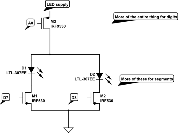
For optimal performance, the design includes current limiting resistors to prevent excessive current draw through the segments, ensuring longevity and reliability of the displays. The configuration of the 7-segment displays allows for versatile visual output, making this circuit suitable for a variety of applications where numerical and alphanumeric information needs to be presented clearly and effectively.The diagram below illustrates the high level connections required to drive a single 7-segment display on the scoreboard. The below circuit was repeated 4 times - once for each of the four 7-segment LED displays. Each circuit takes a single data line as its input (C32 outputs T4-T7), and uses a shared clock signal (C32 output T3) that is common to
all of the 4 LED display circuits. The scoreboard therefore requires 5 pins total on the C32 to operate, along with 5V power, 13. 6V power, and ground. The single input to each 7-segment LED display is not adequate to directly control the operation of the display. To control the segments independently of one another, the scoreboard uses a 74HC164 8-bit serial-in, parallel-out shift register.
This particular shift register operates by performing and AND operation on the two input lines and assigning this logical value to the first output pin of the shift register each time a rising edge is detected on the clock input. The value in the first output subsequently shifts to the second output, and so on down the line. By pulsing the clock 8 times, the full set of 74HC164 outputs can be assigned. With 4 data lines and a shared clock pulse, the C32 can simultaneously control the states of 32 different outputs, and completely change their values in 8 clock pulses.
The only limitation on the use of the shift registers is the requirement that the output circuitry be functionally insensitive to the transient output states which occur when the contents of the register are being changed. In the case of the LED display, these transient states are manifested as almost imperceptible flickering of individual segments during the refresh process.
The choice of a common cathode LED display requires that the individual segments of the LED display be switched from the high side. As each segment of the display, with the exception of the decimal point, comprises 4 individual LEDs, a minimum voltage drop of 6.
8V across the LEDs is needed, with the need for an additional voltage drop across the resistor that is used to limit the current through the segment to the recommended 20 mA. In order to effectively switch this voltage from the high side using a PNP transistor, the 0 to 5V signal from the shift register must be stepped up to a 13.
6V signal, as the LED display will be driven from 13. 6V. To step up the logic signal, an LM339 comparator in an inverting configuration is used, with a reference voltage of 2. 5V at the positive input. Vcc for the comparator is 13. 6V in order to generate an output signal large enough to switch the segments. Since the application is insensitive to small transient signals, A 2k pull-up resistor is used at the open-collector output of the LM339 to ensure a strong `high` voltage.
The output of the LM339 cannot source enough current to directly power the segments of the LED display, which requires 20mA per segment. The output of the LM339 is therefore used to switch a 2N3906 PNP transistor which can handle up to 100 mA.
A single transistor switches current to each individual segment. The current passing through each transistor, and hence through the display, is limited to 20mA by a small (330 ohm) resistor placed in line with the segments. The Ligitek LSD23255-10 displays used for our project are LED arrays in the same 7-segment configuration that is ubiquitous in society, from clocks to price displays to calculators.
Due to the large size of our displays, each segment is actually comprised of 4 individual LEDs, with the exception of the 2 LED decimal point. For our project the decimal point was not needed though, and was therefore not connected. By controlling the sequence of lit and unlit segments through the shift register and switching circuits, different numbers and letters can be displayed.
🔗 External reference
Related Circuits
Due to power limitations, the design options for the flippers were constrained. Typically, pinball machines utilize linear solenoids, which at 12 V and 3 A offer inadequate performance. Conversely, employing DC, servo, or stepper motors posed challenges. To achieve...
The circuit is designed to fit into a small enclosure that can be placed in a backbox at a location of your choice. It requires only three wires: one for the battery positive voltage, one for the +5 volts...
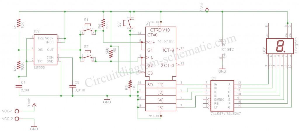
The digital scoreboard circuit is designed to display numerical values ranging from 0 to 9 on a 7-segment display. This display utilizes a common anode configuration. The digital scoreboard circuit operates by controlling a 7-segment display that utilizes a common...
The digital scoreboard circuit is designed to display numerical values ranging from 0 to 9 on a common anode 7-segment display. The circuit employs a 7-segment driver integrated circuit (IC), specifically the 74LS47 or 74LS247. A 555 timer IC...
A scoreboard is located in the center of the room, which will be controlled from backstage. The scoreboard features two individual 3-digit numbers. Whenever the score changes, a sound will be emitted. The simplest, most efficient, and cost-effective solution...

This machine's playfield includes a catapult that launches the pinball, trolls that emerge from the playfield, and an exploding castle featuring a drawbridge and an iron drop-gate. All plastics were replaced with a New Old Stock (NOS) set from...