
megaphone portable

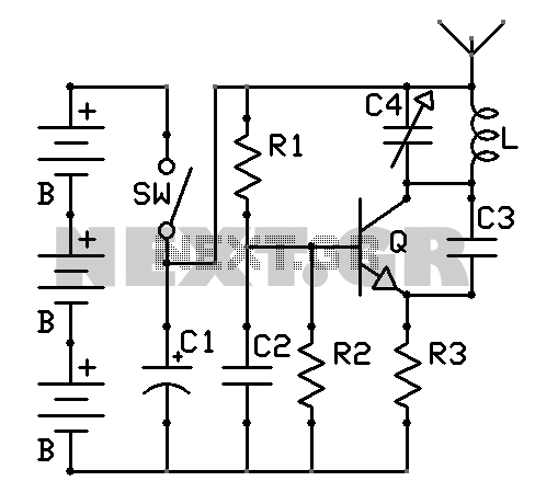
The circuit design incorporates a 555 timer configured in astable mode to generate a square wave signal, which serves as the audio tone output. The frequency of the output can be adjusted by varying the resistor and capacitor values connected to the 555 timer. This configuration allows for tunable sound frequencies that can be emitted through the megaphone, effectively creating a deterrent sound for the aggressive dogs. The output from the 555 timer is insufficient to drive the megaphone directly due to its high power requirements; thus, a MOSFET is employed as a switch to amplify the signal. The MOSFET is connected to the megaphone's power supply, allowing it to handle the higher current needed for operation.
In addition to the basic functionality, the integration of an Arduino-based frequency counter could provide real-time feedback on the frequency being generated, offering the user the ability to fine-tune the output sound. This digital readout would enhance the usability of the device, making it easier to adjust settings on-the-fly. Future iterations of the project may also explore the possibility of programming the Arduino to generate the audio signal directly, although the simplicity and reliability of the 555 timer are appreciated.
The overall design emphasizes safety and effectiveness, ensuring that the device is not harmful to animals while providing a solution to the issue of aggressive dogs in the neighborhood. The project exemplifies a creative approach to problem-solving using basic electronic components and encourages further exploration of the capabilities of the 555 timer in various applications.First, before everyone goes writing me about how vile of a person I am because I made a device that kills helpless animals, please read the entire post. This device does not actually kill or harm dogs or any other living creature in any way shape or form.
Recently I had a problem in the neighborhood whereby a couple of aberrant K9 ²s were getting lose because the irresponsible owner would not repair the hole in his fence that was allowing them to escape. The problem got so bad one day when returning from the grocery store, I found myself trapped in my car under seige by these animals.
Every time I tried to exit my car they would approach me aggressively. Not one to test fate the police were called, but by the time they responded, the animals were no where to be found. It was not uncommon for these animals to get loose several times a week. One day I was listing to the Security Now! podcast and Steve Gibson was describing a story from when he was a kid when he constructed what he called a Portable Dog Killer ( here is a link to the mp3 of that podcast ).
While he didn`t give specifics of the circuit, he did mention that it contained a 555 timer and a piezoelectric speaker. Using my imagination I could piece together what he did. His results with his homemade gadget were spectacular. I began to think What if I took that concept and fed it in to a megaphone. Megaphones are perfect They are designed acoustically to be loud. I quickly ordered up the biggest, loudest megaphone I could find (without breaking the bank). Now I should say I am an amateur with electronics. I am not an engineer or an expert by any means. I can copy a formula for frequency and plug in my own values (such as the formula for freq), but beyond that I am lost.
So my first pass at bread-boarding failed because the output of the 555 could not drive the cone directly. I had read that mosfets can be useful for driving high current devices so I wired one in Success. This is still a work in progress. The name Portable Dog Killer is a a tribute to Steve Gibson. On a quick side note, please check out his site at I highly recommend listening to the podcast linked above, it is supremely entertaining and inspiring for any aspiring maker.
(ATTENTION JUDGES This video is of an early prototype version posted here to show my progress with this. Please see the 2nd video below for the final version of the contest submission) Circuit Boards arrived from BatchPCB, They are great I order 2 they send me 3!
They do this all the time, they sometimes need to fill up a panel, so they send you the extras free of charge. Fortunately Animal Control dealt with the Dogs problem before I had to use this, so my development on this has been put on hold for now.
But should the hounds of hell come knocking on my door, Ill be ready. Well for one I would like to make it louder. I will probably reinstall the original megaphones circuit via a switch. In addition to that, I had worked out an arduino based frequency counter (picture below). I had thought of doing a digital read out of the frequency. I suppose if I do, I could have the arduino generate the tone as well, but what is the fun in that The 555 is so perfect at what it does, it has an infinite number of uses and I am glad I had the opportunity to share this one. I look forward to learning a lot more of what it can do via the submissions to this contest. Thank you for your time. 🔗 External reference
Related Circuits
This circuit is primarily designed to offer a microphone input for standard home stereo amplifiers. Utilizing a battery supply effectively eliminates the risk of low-frequency hum interference from the mains, and simplifies the connection to the amplifier by removing...
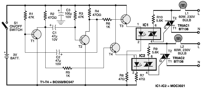
Portable 230V lamp flasher circuit diagram. The circuit is entirely transistorized and powered by a battery. A free-running oscillator circuit is implemented using two low-power, low-noise transistors, T1 and T2. One of these transistors remains in a conducting state...
This small amplifier was intended to be used in conjunction with an electric guitar to do some low power monitoring, mainly for practice, either via an incorporated small loudspeaker or headphones. The complete circuit, loudspeaker, batteries, input and output...
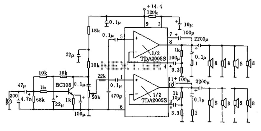
20W bus radio and megaphone circuit utilizing the TDA2005S double low-frequency power amplifier integrated circuit design. The front end can be connected to either a microphone input or a low-frequency radio output voltage amplification stage. Each TDA2005S provides 10W...
There are neighbors who may disturb you with loud televisions or radios. A solution is available. This jammer emits jamming waves that affect the TVs and radios in the neighborhood, so caution is advised. This device is an enhanced...
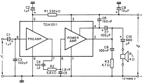
The following schematic illustrates the design of a 4 Watt Amplifier Circuit Diagram intended for portable radio applications, utilizing the TDA1011 integrated circuit from Philips Semiconductor. The 4 Watt Amplifier Circuit is designed to provide audio amplification in portable radio...