
Metal detector 8

The metal detector circuit operates through a systematic arrangement of components that work together to achieve effective metal detection. The detection circuit begins with the detection coil (L), which generates an electromagnetic field. When metallic objects enter this field, they induce a change in the field, which is then picked up by the transistor (V1). This change is amplified and processed through the resistors (R1-R3) and capacitors (C1-C5), ensuring that the signal is strong enough for further processing.
The PLL phase-locked loop circuit, utilizing the MC4046B integrated circuit (IC1), plays a crucial role in frequency stabilization and signal processing. It receives the output from the detection circuit and locks onto the frequency of the detected signal. This circuit includes resistors (R4-R8) and capacitors (C7-C11) that are carefully selected to ensure optimal performance and stability of the PLL operation.
The sound alarm circuit is activated when the PLL circuit detects a metal object. The second transistor (V2) acts as a switch, allowing current to flow to the buzzer (HA) when the detection condition is met. The comparator amplifier integrated circuit (IC2) processes the signal from the PLL circuit to determine whether it exceeds a certain threshold, ensuring that only significant detections trigger the alarm. The additional resistors (R8-R14) in this circuit help to set the gain and response characteristics of the alarm system.
Overall, the combination of these circuits results in a reliable metal detection system capable of identifying various types of metal objects in different environments. The careful selection of components, including resistors, capacitors, and integrated circuits, is essential for achieving the desired sensitivity and accuracy in detection. The design can be further enhanced with adjustments to the variable resistor (RP) and the fine-tuning capacitor (C11) to cater to specific detection requirements.This example describes a metal detector which uses a PLL (phase locked loop) digital integrated circuit MCl4046, it can emit the alarm signal when detects metal objects, and it can determine detected material which is based on current meter`s instructions. The device is suitable for detection of nails in wood, the metal objects in sand, wires in w alls and so on. The working principle. The metal detector circuit is composed of dection circuit, PLL phase-locked loop circuit and sound alarm circuit, it is shown in Figure 8-74. Detectioncircuit is composed of the detection coil L, the transistor Vl, resistors Rl-R3, capacitors Cl-C5.
PLL phase-locked loop circuit consists of integrated circuit ICl, resistors R4-R8, capacitor C7-Cll. Sound alarm circuitis composed ofthe transistor V2, comparing amplifier integrated circuit IC2, buzzer HA, resistors Rg-R14. Rl-Rl4 use 1/4W carbon film resistors or metal film resistors; Rl5 uses 1/2W metal film resistors. RP uses small potentiometer or variable resistor. Cl, C2, C7-C9, Cl2 and C13 select monolithic capacitors; C3-C6 and ClO use high-frequency ceramic capacitors; C11 uses fine-tuning capacitor (semi variable capacitor).
Vl and V2 use S9018 or 2SCl815 NPN silicon transistor. ICl uses MCl4046B PLL PLL CD4046 integrated circuit; IC2 uses PPC393C type operational amplifier integrated circuit. 🔗 External reference
Related Circuits

Alcohol Detector, a Microcontroller 8051-Based Project. This project focuses on detecting the presence of alcohol, which can be highly beneficial for identifying alcohol consumption levels. The Alcohol Detector project utilizes the 8051 microcontroller architecture, which is well-known for its versatility...
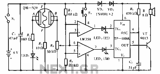
The QM-NJ9 is an alcohol sensor that detects the presence of alcohol by measuring the resistance values between points A and B. When alcohol is detected, the resistance decreases, leading to an increase in potential at point B. As...
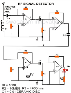
A simple electronic circuit project is presented that can be constructed by any school student for display at a school science fair. The proposed circuit is a high-gain operational amplifier (op-amp) amplifier designed to detect the slightest RF disturbances...
The metal detector described in the example can detect metal objects made of highly permeable magnetic substances. The circuit operates based on several components: a power circuit, a sine wave oscillator, a PLL (phase-locked loop) circuit, and a hybrid...
With the help of a simple ceramic piezoelectric detector, it is possible to assemble an interesting and useful impact sensor unit, which can be used to detect... An impact sensor unit utilizing a ceramic piezoelectric detector operates by converting mechanical...
The hardware for this project had three main components: laser gun assembly, detector unit, control pad. The detector unit's function was to simply detect a laser pulse over a small area sent by the laser driver circuit on the...