
Metal detector 2
The metal detector circuit is designed to efficiently identify metal objects by utilizing a combination of electronic components that work in unison. The power circuit is crucial for supplying the necessary voltage and current to the entire system, ensuring that all components operate effectively. The inclusion of filter capacitors (Cl and C2) helps to stabilize the power supply by reducing voltage fluctuations, which is essential for maintaining the performance of sensitive electronic circuits.
The sine wave oscillator circuit plays a pivotal role in generating the alternating current (AC) signal that is necessary for the operation of the detecting coil (L). This coil is responsible for creating a magnetic field that interacts with nearby metal objects. The oscillation frequency can be adjusted by changing the values of capacitors (C3-C5) and resistors (Rl and R2), allowing for fine-tuning of the detector's sensitivity and range.
The PLL circuit is essential for maintaining a consistent frequency and phase relationship between the transmitted and received signals. It utilizes a dual time-base integrated circuit, which helps in demodulating the signal received from the detecting coil. The resistors (R3) and potentiometers (RPl) in this circuit allow for precise adjustments to the loop characteristics, enhancing the detector's ability to differentiate between various types of metal.
The hybrid amplification circuit is designed to amplify the weak signals received from the detecting coil. This is achieved through the use of transistors (V2 and V3) and resistors (R4-R6), which boost the signal strength to a level that can be accurately measured by the ammeter (PA). The potentiometer (RP2) allows for further adjustment of the amplification level, providing the user with control over the sensitivity of the detector.
Overall, this metal detector circuit exemplifies a well-structured approach to metal detection, employing a range of electronic components that work together to achieve effective and reliable performance. The careful selection of resistors, capacitors, and other components ensures that the circuit operates within its intended parameters, making it suitable for various applications in metal detection.This metal detectors described in the example can be used to detect metal objects with high permeable magnetic substances. The working principle. The metal detector circuit is composed of the power circuit, sine wave oscillator, PLL phase-locked loop circuit and hybrid amplification circuit, it is shown in Figure 8-68.
Power circuit is composed of the battery GBl, GB2, filter capacitor Cl, C2, and the power switch S (Sa, Sb). Sinusoidal oscillator circuit consists of transistors Vl, detecting coil L, capacitor C3-C5 and resistors Rl, R2. PLL circuit is composed of dual time-base integrated circuit and resistors R3, potentiometers RPI, capacitors C6-C8.
The hybrid amplification circuit is composed of the transistors V2, V3, resistors R4-R6, potentiometer RP2 and ammeter PA. Rl-R6 use l/8W or 1/4W carbon film resistors. RPl uses multi-turn precision potentiometer; RP2 uses general lap synthetic membranes potentiometer. Cl and C2 select electrolytic capacitors with voltage in 16V; C3-C5 and C8 select monolithic capacitors; C6 and C7 select high-frequency ceramic capacitors.
🔗 External reference
Related Circuits
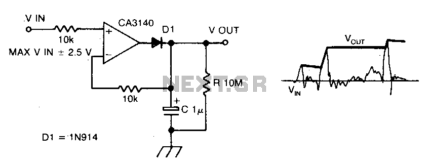
The circuit employs negative feedback exclusively for positive signals. The inverting input receives feedback only when diode D1 is forward biased, which occurs solely with positive input signals. As the positive input signal increases, the output of the operational...

Two precision temperature sensors are utilized to measure a slight temperature difference. When airflow is present, the self-heating of the LM335 is minimized, resulting in an unequal output from the two temperature sensors. This disparity is further amplified by...
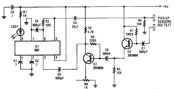
A simple proximity detector electronic project can be designed using this schematic circuit. This project utilizes a tone decoder integrated circuit (NE567) that provides a signal with a frequency of approximately 100 kHz. When an object is placed near...

The detector is designed to sense and signal to another circuit when an appliance is connected to the mains voltage. An optocoupler, identified as IC1 in the circuit, is utilized for this purpose. The light-emitting diode within the optocoupler...

This circuit is designed for sound detection and generates an output signal when sound is detected. This output can trigger another circuit that activates an alarm, making it suitable for security applications. The circuit employs a condenser microphone to...
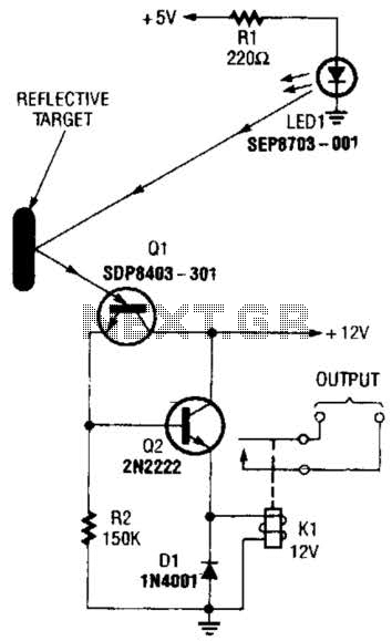
A reflector isolator detects the presence of an object by bouncing light off of it. This technique is useful in circuits that detect when an object is close enough to the sensor. A reflector isolator is a type of optical...
Warning: include(partials/cookie-banner.php): Failed to open stream: Permission denied in /var/www/html/nextgr/view-circuit.php on line 713
Warning: include(): Failed opening 'partials/cookie-banner.php' for inclusion (include_path='.:/usr/share/php') in /var/www/html/nextgr/view-circuit.php on line 713