
laser gun, detector unit and control pad

The project consists of three integral components: the laser gun assembly, the detector unit, and the control pad.
The laser gun assembly is designed to emit a focused laser beam, which is generated by a laser driver circuit. This circuit typically includes a power source, such as a battery pack, and a laser diode. The laser gun must be ergonomically designed for ease of handling during gameplay, and it should include a trigger mechanism that activates the laser emission when pressed. The power circuit must be efficient to ensure prolonged playtime without frequent battery changes.
The detector unit is responsible for sensing the laser pulses emitted by the opposing player's laser gun. It incorporates a photodiode or phototransistor that is sensitive to the wavelength of the laser used. This unit must be calibrated to detect the laser pulse over a defined area, ensuring that players are rewarded for accurate shots. The detector unit also requires a microcontroller to process incoming signals and determine if a hit has occurred. Upon detecting a laser pulse, the microcontroller will trigger a response in the control pad.
The control pad serves multiple purposes. It keeps track of the score, indicating successful hits and missed shots. It is equipped with an auditory output device, such as a small speaker, to play sound effects that signify a hit. Additionally, the control pad is designed to communicate wirelessly with other control pads using RF (radio frequency) technology. This feature allows for real-time score updates and enhances the multiplayer experience. Each control pad must be programmed to handle incoming signals and update scores accordingly.
The hardware setup should be modular, allowing for easy duplication of components for each player in the game. This modularity is critical for multiplayer scenarios, as it ensures that each player has an independent laser gun and control pad, thus eliminating the need for cumbersome wiring between players. The use of an independent power source for the laser gun enhances portability and user experience.
In summary, the project integrates these three components into a cohesive system that facilitates an engaging laser tag experience. Each component must be designed with attention to detail in terms of functionality, user interface, and reliability to ensure a seamless and enjoyable game for all participants.The hardware for this project had three main components: laser gun assembly, detector unit, control pad. The detector units function was to simply detect a laser pulse over a small area sent by the laser driver circuit on the laser gun assembly.
In reaction to this detection the control pad would keep correct score, play a short sound to indicate a hit, and transmit a successful hit via an RF frequency to the other players control pad where it would be received and displayed. These three components joined together would complete the laser transmission, detection, and control for use in a typical laser tag environment; however, due to the multiplayer nature of the game, each hardware component had to be duplicated for the second player to use.
Our general plans was to have a stand-alone laser gun driven by its own independent power source, and have this laser work in conjunction with a combined laser detector and control module. This would allow players to not have the dreaded cable extension f 🔗 External reference
Related Circuits
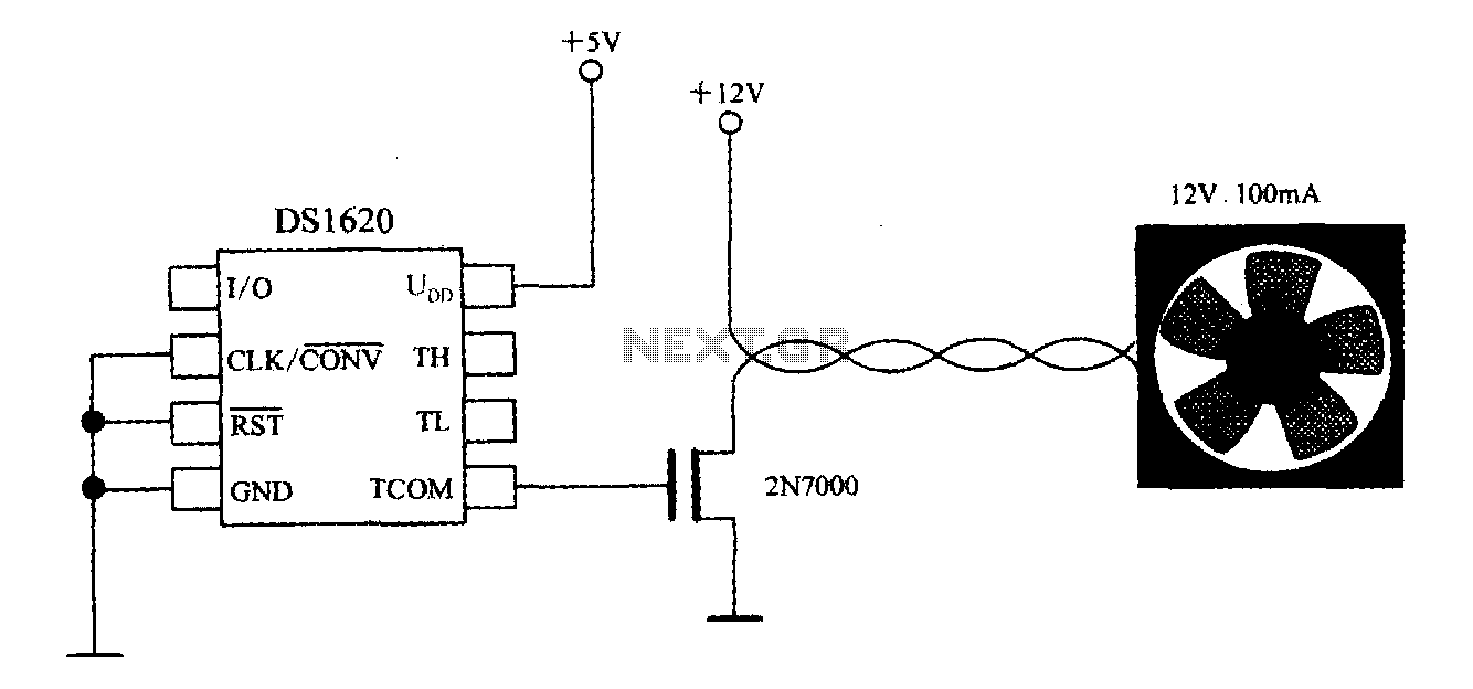
The DS1620, in conjunction with a microprocessor, is utilized to monitor temperature. By controlling the fan, the thermal conditions of the chip can be adjusted to establish a temperature control circuit as illustrated in the accompanying figure. The system...
This set of two circuits forms the basis for a very simple light wave transmitter. A LASER beam is modulated and then aimed at a receiver that demodulates the signal and then presents the information (voice, data, etc.). The...
The circuit presented utilizes a two-transistor "flasher" to generate triggering pulses, replacing the traditional unijunction transistor design. This configuration allows for a broad range of control with minimal hysteresis and sensitivity to line voltage. Two diodes rectify the line...
The old and omnipresent NE555 can be very good at something it was not meant for: driving relays or other loads up to 200 mA. The picture shows an example circuit: if the input level rises over 2/3 of...
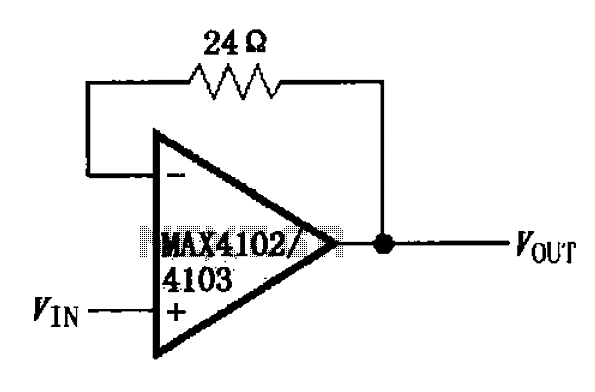
The MAX4102/4103 unity gain buffer circuit is illustrated in the figure. This circuit incorporates a small resistor (24 ohms) positioned in the feedback loop of the amplifier, which forms a unity gain buffer. Additionally, it achieves a maximum bandwidth...
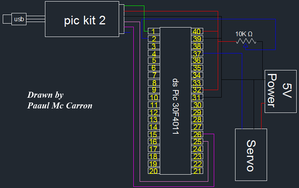
One of the motors utilized in the module is a servo motor. A servo motor is a compact motor that allows for precise positioning at various angles. It is equipped with internal circuitry that automatically maintains the specified angle....