
Metal Detector Cirduit with IC TDA0161

The metal detector circuit operates on the principle of eddy current induction, where a coil (L1) generates a magnetic field that induces currents in nearby metallic objects. As a metallic object approaches, the eddy currents generated within it lead to variations in the magnetic field, which in turn influences the oscillation characteristics of the circuit. The circuit is designed with an integrated circuit (IC) that includes a feedback mechanism to stabilize the oscillation frequency based on the detected eddy current losses.
The circuit's performance is heavily reliant on the tuning of the external components, specifically the resistor R3 and the trimmer potentiometer PR1. These components allow for precise adjustments to the circuit's threshold sensitivity, enabling the detection of metallic objects at varying distances. The negative resistance behavior of the IC between pins 3 and 7 is crucial for maintaining oscillation, as it counteracts losses in the tuned circuit.
When a metallic object is detected, the loss resistance Rp decreases, leading to a higher supply current (ICC(close)). This change can be monitored and utilized to trigger an alert or activate additional circuitry, such as an indicator light or a sound alarm. Conversely, when the metallic object is removed, the supply current drops (ICC(remote)), indicating the absence of a metallic presence.
The design of the metal detector circuit is robust, allowing for operation independent of supply voltage variations, provided that the voltage remains within specified limits. This feature enhances the circuit's versatility for various applications, including security, treasure hunting, and industrial metal detection. The careful selection of components and the tuning of the circuit parameters ensure reliable performance across different environmental conditions and object types.The Metal detector project is designed for metallic body detection by sensing variations in high frequency Eddy current losses. Using an externally-tuned circuit, they act as oscillators. The output signal level is altered by an approaching metallic object. The output signal is determined by supply current changes. Independent of supply voltage, this current is high or low, according to the presence or absence of a closely located metallic object Between pins 3 and 7, the integrated circuit acts like a negative resistor with a value equal to that of the external resistor R3 and trimmer potentiometer PR1 (connected between pins 2 and 4). The oscillation stops when the tuned circuit loss resistance (Rp) becomes smaller than R3. As a result, ICC(close) = 10mA (pins 1 and 6). The oscillation is sustained when Rp is higher than R3, and ICC(remote) = 1mA (pins 1 and 6). Eddy currents induced by coil L1 in a metallic body determine the value of Rp. 🔗 External reference
Related Circuits
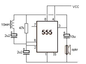
A simple metal detector circuit can be implemented using a 555 timer chip. The schematic diagram illustrates that this project requires only a few external electronic components. The metal detector circuit utilizing a 555 timer operates in astable mode, generating...
Similar to a field strength meter, an RF detector circuit serves as a valuable project for detecting nearby RF signals. The circuit presented here is capable of detecting a wide range of RF frequencies and provides an alarm when...
Humidity detector circuit electronic project using common electronic parts The humidity detector circuit is a project designed to measure and indicate the level of humidity in the environment. This circuit utilizes commonly available electronic components, making it accessible for hobbyists...
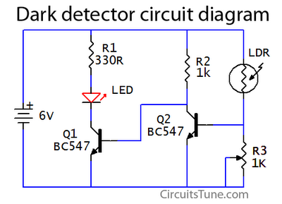
This is a basic dark detector or sensor circuit diagram based on a photoresistor (LDR) and a few components. The dark detector circuit utilizes a photoresistor (LDR) as the primary sensing element. The LDR is a light-dependent resistor that changes...
This project outlines a simple water detector circuit. The components required for this project include the following: 1. One IC 555 timer, and 2. A small-sized general-purpose relay. The water detector circuit utilizes the IC 555 timer configured in a...

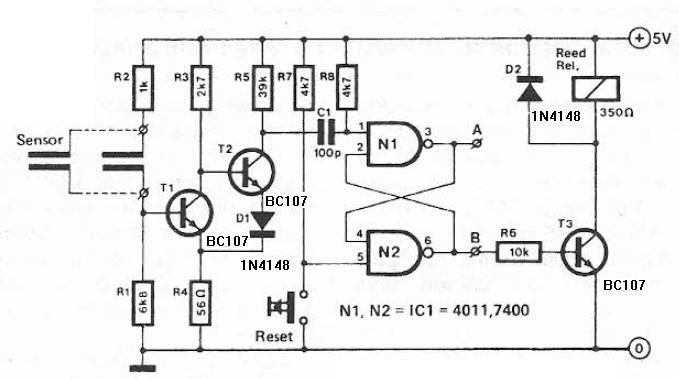
Voltage across resistor Rl is only present when inputs A and (2- to 3-V amplitude) occur simultaneously. A brief overlap of less than 1 microsecond is enough to trigger the silicon-controlled switch (SCS). Coincidence of negative inputs is detected...