
Metal Detector DIY Circuit

The CS209A metal detector circuit operates based on the principle of inductive reactance, where the oscillation frequency of the LC circuit is influenced by the presence of metallic objects. The oscillator generates a signal that drives the coil, which acts as the inductor in the circuit. When the coil is near metal, the inductance increases, leading to a shift in the oscillation frequency. This frequency shift is detected by the CS209A, which triggers the output components: LED 1 and the buzzer.
The circuit includes a variable resistor (VR1) that allows for calibration of the sensitivity. Initially, VR1 is set to a position that ensures the circuit is responsive to metal detection. As the user moves the coil away from metal objects, VR1 is adjusted to minimize false positives, ensuring that both the LED and buzzer remain inactive when no metal is detected.
In terms of construction, the coil should be wound carefully to achieve the specified inductance of 100 µH. The choice of wire gauge and the number of turns will affect the performance of the detector. The circuit should be housed in a suitable enclosure to protect it from environmental factors and to prevent accidental adjustments to VR1 during operation.
Overall, this DIY metal detector circuit is a practical application of basic electronic principles, providing an accessible project for hobbyists and electronics enthusiasts. Proper tuning and calibration are essential for optimal performance, and the simplicity of the design allows for easy modifications and enhancements based on user experience.The heart of this diy metal detector circuit is CS209A. Themetal detectorit is build with one coil of 100uH. CS209A has one oscillator wich forms an LC circuit, the inductance of the coil will change when it is near metal objects. LED 1 will light and the buzzer turns on when the coil is changing inductance. The setup is easy, VR1 is adjusted ( away from any metal objects ) so that LED 1 will light and the buzzor sounds on, and then VR1 will be trimmed until led and buzzer are off. 🔗 External reference
Related Circuits
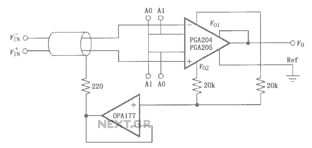
The circuit illustrated by the PGA204/205 pertains to the shield drive circuit shown in the figure. It is demonstrated through interference theory and practical application that the cable shield, when transmitting weak signals, maintains a certain potential. This configuration...
This is a very basic infrared detector/emitter circuit. One major downside of this circuit, is that ambient infrared light will interfere with its detecting obstacles. The described circuit functions as a basic infrared (IR) detector and emitter system, commonly utilized...

There are issues with simulating this circuit on Proteus. Please review it to ensure no errors were made. The user is also a novice. The circuit simulation in Proteus can often present challenges, especially for those who are new to...

Two telephones can be used as an intercom by utilizing this circuit. Older style rotary phones that are non-electronic may be the most suitable for this application. Additionally, handsets alone can be powered in this manner. This intercom circuit allows...
The circuit does not fail under slight variations, even if the input/output electric current characteristics are exceeded. Failure occurs only during a short circuit or extreme conditions at the output. The operation of the circuit is explained as follows:...
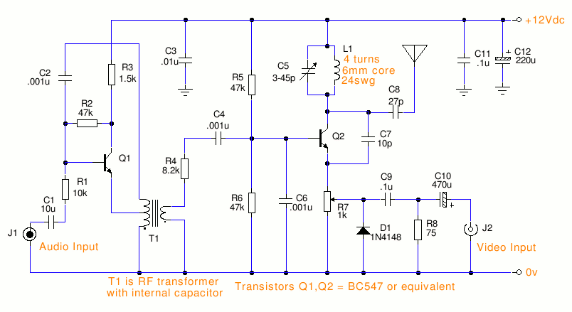
This is a small TV transmitter circuit that transmits in VHF, utilizing negative sound modulation and PAL video modulation. It is suitable for countries that use the B and G system. T1 refers to a type of transformer. The...