
Metal detector schematic circuit using CS209A

The metal detector circuit utilizing the CS209A integrated circuit is designed to detect metallic objects through the principle of electromagnetic induction. The CS209A is a specialized IC that facilitates the detection and processing of signals generated by the presence of metal.
The circuit typically consists of several key components: a power supply, the CS209A IC, an oscillator circuit, a search coil, and an audio output device such as a speaker or buzzer. The power supply provides the necessary voltage and current for the operation of the circuit, usually in the range of 5V to 12V.
The oscillator circuit is critical, as it generates a high-frequency signal that is transmitted through the search coil. The search coil is a loop of wire that creates a magnetic field when current flows through it. When a metallic object enters this magnetic field, it induces eddy currents in the metal, which in turn create their own magnetic field. This interaction alters the original signal from the oscillator, which is then picked up by the CS209A.
The CS209A processes the received signal and determines whether it corresponds to the presence of metal. If metal is detected, the IC activates the audio output device, providing an audible alert to the user. This alert can be adjusted in volume or tone, depending on the design of the circuit.
Additional components may include resistors and capacitors to filter signals and stabilize the circuit, as well as potentiometers for tuning sensitivity and discrimination between different types of metals. The layout of the circuit should be designed to minimize noise and interference, ensuring reliable operation in various environments.
In summary, the metal detector circuit using the CS209A combines several electronic components to create a functional and effective device for detecting metal objects, leveraging the principles of electromagnetism and signal processing.Metal detector schematic circuit using CS209A and few electronic components 🔗 External reference
Related Circuits
The 555 timer on the right is configured as an alarm sound generator, while the second 555 timer on the left operates as a 1 Hz astable multivibrator. The output from the left timer modulates the frequency of the...
Because it uses few parts, a printed circuit board is not necessary; components can simply be soldered to one another. However, a box is desirable for operating convenience. The case and aerial from a discarded toy walkie-talkie was used...

The FM radio circuit is represented by a double-gate MOS field-effect transistor. The high-frequency amplifier is a bipolar MOS field-effect transistor amplifier consisting of transistors VT1 and VT2. VT3 serves as the mixer. The local oscillator is formed by...
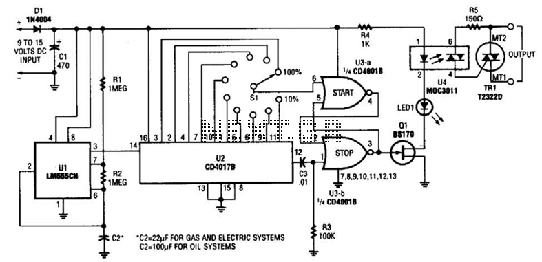
A timer (LM555CN) and decode counter are utilized to generate duty cycles ranging from 10% to 100% for controlling the operational time of a heating system. V2 operates as a decode counter that can be adjusted for duty cycles...

Figure 1 illustrates a circuit that utilizes a single +V power supply and a voltage output Digital-to-Analog Converter (DAC) known as the AD5620. The DAC is controlled via an SPI port, with its output ranging from 0 V to...

The following circuit illustrates a 20 dB VHF amplifier circuit diagram utilizing the BF197 transistor. Features include a simple circuit design. The 20 dB VHF amplifier circuit is designed to amplify very high frequency signals, making it suitable for applications...