
Metal Detector TDA 2822

The described metal detector circuit utilizes the superheterodyne principle, which is effective for frequency mixing and signal detection. The two RF oscillators, both operating at a fixed frequency of 5.5 MHz, play a crucial role in the detection process. The first oscillator, built around transistor T1 (BF 494), incorporates a 5.5 MHz ceramic filter that enhances signal stability and clarity, commonly found in television sound intermediate frequency (IF) stages. The second oscillator is a Colpitts configuration, utilizing transistor T3 (BF 494) and an inductor L1, which is essential for generating the necessary oscillation frequency. This inductor is constructed with 15 turns of 25 SWG wire wound on a 10 cm diameter air-core former, ensuring proper inductance values for the desired frequency range.
The mixing process occurs in the transistor T2 (another BF 494), where the outputs of both oscillators are combined. The resulting difference frequency, known as the beat frequency (Fx - Fy), is critical for detecting metal. This output is processed through diodes D1 and D2 (both OA 79), which rectify the AC signal into a pulsating DC waveform. A low-pass filter comprising a 10 kΩ resistor (R12) and two 15 nF capacitors (C6 and C10) smooths the pulsating DC signal, preparing it for amplification.
The amplified output is managed by the audio frequency (AF) amplifier IC1 (2822M), which drives an 8-ohm, 1W speaker. The circuit's performance hinges on the precise alignment of the two oscillators, achieved through the trimmer capacitor VC1. When both oscillators are perfectly matched, the beat frequency is zero, resulting in silence from the speaker. However, when the search coil (L1) detects metal, the inductance changes, leading to a shift in the frequency of the second oscillator. This frequency deviation results in a non-zero beat frequency, thus activating the speaker and signaling the presence of metal. This design showcases the effectiveness of superheterodyne circuits in metal detection applications, emphasizing the importance of frequency stability and precise tuning for optimal performance.The circuit described here is that of a metal detector. The opera- tion of the circuit is based on superheterodyning principle which is commonly used in superhet receivers. The circuit utilises two RF oscillators. The frequencies of both oscillators are fixed at 5.5 MHz. The first RF oscillator comprises transistor T1 (BF 494) and a 5.5MHz ceramic filter commonly used in TV sound-IF section.
The second oscillator is a Colpitts oscillator realised with the help of transistor T3 (BF494) and inductor L1 (whose construction details follow) shunted by trimmer capacitor VC1. These two oscillators frequencies (say Fx and Fy) are mixed in the mixer transistor T2 (another BF 494) and the difference or the beat frequency (Fx-Fy) output from collector of transistor T2 is connected to detector stage comprising diodes D1 and D2 (both OA 79). The output is a pulsating DC which is passed through a low-pass filter realised with the help of a 10k resistor R12 and two 15nF capacitors C6 and C10.
It is then passed to AF amplifier IC1 (2822M) via volume control VR1 and the output is fed to an 8-ohm/1W speaker. The inductor L1 can be constructed using 15 turns of 25SWG wire on a 10cm (4-inch) diameter air-core former and then cementing it with insulating varnish.
For proper operation of the circuit it is critical that frequencies of both the oscillators are the same so as to obtain zero beat in the absence of any metal in the near vicinity of the circuit. The alignment of oscillator 2 (to match oscillator 1 frequency) can be done with the help of trimmer capacitor VC1.
When the two frequencies are equal, the beat frequency is zero, i.e. beat frquency=Fx-Fy=0, and thus there is no sound from the loudspeaker. When search coil L1 passes over metal, the metal changes its inductance, thereby changing the second oscillators frequency. So now Fx-Fy is not zero and the loudspeaker sounds. Thus one is able to detect presence of metal 🔗 External reference
Related Circuits

The following circuit illustrates a Simple Moisture Detector Circuit Diagram. This circuit is based on the 4093 IC. Features include the ability to detect a certain level of moisture. The Simple Moisture Detector Circuit utilizes the 4093 integrated circuit, which...
This is a stereo power amplifier circuit that operates at up to 22W per channel, resulting in a total output of 2x22W. A few external components are required to support the main component, the TDA1554. A heatsink on the...
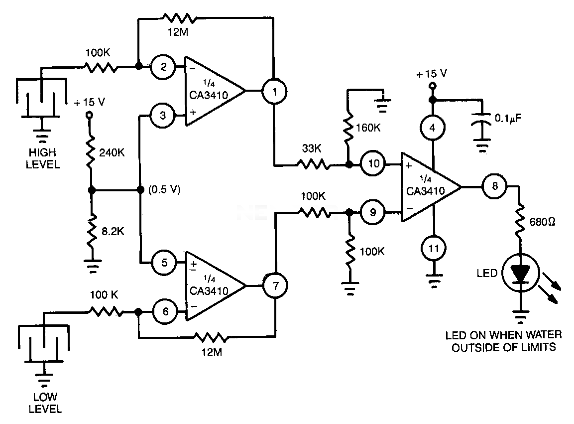
Utilizes the CA3410 quad BiMOS operational amplifier to detect small currents. Due to the low input current of the op-amp, a current as small as 1 pA flowing through the sensor will cause the converter's output to vary by...
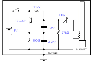
This basic oscillator detects the Earth's magnetic field. A ferrite rod and coil are repurposed from an old Medium Wave receiver, with a small magnet affixed to one end. The device is tuned to a medium wave commercial station...
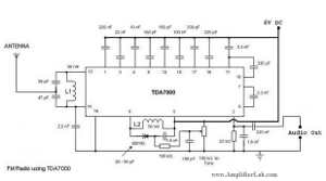
The following circuit illustrates a Single Chip FM Radio Circuit. This circuit is based on the IC TDA 7000 or TDA 7400. Features include a low-cost FM radio circuit. The Single Chip FM Radio Circuit utilizing the TDA 7000 or...
The circuit is designed for speech activity detection in telephone lines. This detection is particularly beneficial for half-duplex conversations between two stations, for simultaneous transmission of voice and data over the same pair of cables by interspersing data within...