
Garden timer circuit with CD4000
A momentary push button, labeled "Resync" is connected to the output of the 10k and 6 pf low pass filter. When the button is pressed, it pulls the reset inputs of the CD4040's and the clock input of the CD4013 high to start a 24 hour timing cycle. The additional l0k resistor in series with the output of the 10k and 6pf low pass filter it to further limit current from the pushbutton to the input of the CD4012, which normally spends all but a few microseconds each day sitting at ground. I use the Resync button to set the time of day that the watering cycle starts.
The CD4013 latch, the output of which (pin 1) goes high to turn on the valve, is reset 34 minutes after the CD4040's are reset, thus turning off the valve. The pulse to turn off the valve 34 minutes after the watering cycle starts, appears on Q1 of the second CD4040. If I wanted to the watering period to be 68.264 minutes, I would use Q2 (pin 7) of the second CD4040. If I wanted 16 minutes, I would have used Q12 of the first CD4040. Moving the connection to the reset input of the CD4013 (pin 4) one flip-flop to the left in the CD4040 counter chain cuts the watering period in half. Moving the connection to the right one flip-flop doubles the watering period.
Valve Solenoid Power Control
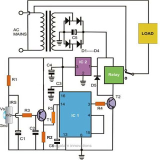
A full-wave bridge rectifier is placed effectively in series with the 24 VAC from the power transformer and the watering valve. The AC signal passes through the AC terminals of the bridge, while the negative terminal is connected to chassis ground and the positive terminal is connected to the drain of a BUZ-73 MOSFET. While the BUZ-73 is off, current does not pass through the valve, and the water is off. When the output of the CD4013 (pin 1) goes high, turning on the BUZ-73, current also passes through the AC terminals of the diode bridge and through the valve solenoid.
The gate of the BUZ73 is connected to the output of the CD4013 (pin 1) through two switches, which allow setting the valve solenoid OFF, ON, or connected to the daily watering cycle timer. This last position is the normal operating position. The OFF and ON positions are for maintenance and troubleshooting. The output of the two switches also connects to a 2N4401 buffer, a dropping resistor, and a yellow LED. The yellow LED is on whenever the valve solenoid is on. A 100k resistor connects the gate of the BUZ-73 to chassis ground to keep the gate from floating in case one of the switches does not get slid all the way to one position or another, or in case a switch becomes intermittent.
There are two series connected 14 VAC metal oxide varistors across the AC terminals of the diode bridge and another pair of series connected 14 VAC metal oxide varistors across the drain and source of the BUZ-73 MOSFET. The purpose of these metal oxide varistors is to protect the diode bridge and the BUZ-73 MOSFET from voltage surges that might appear in either the AC line or the wiring to the valve solenoid.
A 1k resistor between the gate of the BUZ-73 MOSFET and the rest of the circuit limits current that might capacitively couple from a fast rising voltage spike on the drain of the FET to the gate. A zener diode from the gate to ground will limit the gate voltage in the case of such a voltage spike. The .015 microfarad mylar film capacitor across the drain and source of the BUZ-73 MOSFET is there to reduce the amplitude of induced spikes.
5.1 Volt Zener Power Supply
One end of the 24VAC power transformer secondary connects to chassis ground through one of the diodes in the full wave diode bridge when that end of the transformer secondary swings through the negative half of the power supply line cycle. At the same time, the other end of the secondary swings positive. The voltage on this second end of the transformer secondary is rectified by a 1N4007, and passed through a 728 Ohm 2 Watt resistor to supply current to the sprinkler timer circuit. A zener diode limits the voltage at this point to 5.1 volts. Three 220 microfarad capacitors mounted around the circuit board provide plenty of filtration so that there is negligible ripple on the 5.1 volt power supply.
The timer circuit utilizes a CD4060 IC, which features an integrated oscillator and a 14-stage binary counter. The oscillator is configured with a 32768 Hz crystal oscillator, which establishes a stable frequency input for the counter. The 10 MΩ resistor between pins 10 and 11 of the CD4060 biases the internal inverter, allowing it to operate in the analog region. The 330 kΩ resistor in series with the crystal ensures that the crystal is adequately powered without exceeding its limits. The output from the 14th flip-flop of the CD4060 provides a 2 Hz square wave signal, which is used to drive a green LED through a 2N4401 buffer, indicating operational status.
The two CD4040 counters are configured to divide the 2 Hz signal further to generate a 24-hour cycle and a 34-minute watering period. The CD4012 NAND gate decodes the output of the CD4040 counters, providing a reset signal that synchronizes the counters after 24.0355 hours. The CD4013 dual D latch is employed to control the solenoid valve, activating it when the output of the latch goes high.
To facilitate a manual reset, a momentary push button labeled "Resync" is connected to the output of a low-pass filter formed by a 10 kΩ resistor and a 6 pF capacitor. This filter smooths the reset pulse to ensure reliable operation. The additional 10 kΩ resistor limits current from the push button to the CD4012, which typically remains grounded.
The timer's watering cycle is precisely controlled, with the CD4013's output being reset 34 minutes after activation. This timing can be adjusted by changing connections to different outputs of the CD4040 counters, allowing for variable watering durations.
The valve solenoid is powered through a full-wave bridge rectifier connected to a 24 VAC transformer. The BUZ-73 MOSFET acts as a switch, controlled by the output of the CD4013. The system incorporates switching options for maintenance purposes, along with visual indicators like a yellow LED to confirm solenoid activation.
To protect sensitive components from voltage spikes, metal oxide varistors are placed across critical points in the circuit. A 1 kΩ resistor limits gate current to the BUZ-73, while a zener diode safeguards against excessive gate voltage. The capacitor across the MOSFET reduces the effects of induced voltage spikes.
The power supply for the timer circuit is derived from the 24 VAC transformer, with a 1N4007 diode rectifying the voltage. The output is filtered and regulated to provide a stable 5.1 V supply, ensuring reliable operation of the timer circuit with minimal ripple, courtesy of three 220 µF capacitors.The resulting timer circuit is made from a CD4060, includes an oscillator and a 14 stage binary counter, two CD4040's, which are 12 stage binary counters, a CD4012 Dual Nand gate and a CD4013 Dual D Latch. The CD4060 is connected to a 32768 Hz ECS 3X8 tuning form crystal. The 10 Meg Ohm resistor between CD4060 pins 10 and 11 are to bias the internal inverter into its analog region, and the 330 K resistor in series with the crystal is to limit the power to the crystal.
This setup is directly from the ECS data sheet. The output of the 14th flip flop in the CD4060 appears on pin 3, and it is a 2 Hz square wave. A 2N4401 buffer drives a green LED with this square wave. When I see it blinking through the plastic window of the Irrigation System Controller housing, I know that power is on, and that at least the oscillator and first 14 counter stages are working. The CD4040's that follow the CD40406 divide the 2 Hz pulses to get the 24 hour cycle and the 34 minute watering period. When the counter counts up to 24.0355 hours, as decoded by the CD4012, both of the CD4040's are reset and the output of the CD4013 (pin 1) is set high to turn on the valve solenoid.
To get a wide enough pulse to assure that all of the flip-flops inside the CD4040's are reset, the reset pulse from CD4012 pin 13 is passed through a low pass filter made of a 10k resistor and a 6 pf capacitor. A momentary push button, labeled "Resync" is connected to the output of the 10k and 6 pf low pass filter.
When the button is pressed, it pulls the reset inputs of the CD4040's and the clock input of the CD4013 high to start a 24 hour timing cycle. The additional l0k resistor in series with the output of the 10k and 6pf low pass filter it to further limit current from the pushbutton to the input of the CD4012, which normally spends all but a few microseconds each day sitting at ground.
I use the Resync button to set the time of day that the watering cycle starts. The CD4013 latch, the output of which (pin 1) goes high to turn on the valve , is reset 34 minutes after the CD4040's are reset, thus turning off the valve . The pulse to turn off the valve 34 minutes after the watering cycle starts, appears on Q1 of the second CD4040.
If I wanted to the watering period to be 68.264 minutes, I would use Q2 (pin 7) of the second CD4040. If I wanted 16 minutes, I would have used Q12 of the first CD4040. Moving the connection to the reset input of the CD4013 (pin 4) one flip-flop to the left in the CD4040 counter chain cuts the watering period in half.
Moving the connection to the right one flip-flop doubles the watering period. Valve Solenoid Power Control A full-wave bridge rectifier is placed effectively in series with the 24 VAC from the power transformer and the watering valve. The AC signal passes through the AC terminals of the bridge, while the negative terminal is connected to chassis ground and the positive terminal is connected to the drain of a BUZ-73 MOSFET.
While the BUZ-73 is off, current does not pass though the valve, and the water is off. When the output of the CD4013 (pin 1) goes high, turning on the BUZ-73, current also passes through the AC terminals of the diode bridge and through the valve solenoid. The gate of the BUZ73 is connected to the output of the CD4013 (pin 1) through two switches, which allow me set valve solenoid OFF, ON, or connected to the daily watering cycle timer.
This last position is the normal operating position. The OFF and ON positions are for maintenance and troubleshooting. The output of the two switches also connects to a 2N4401 buffer, a dropping resistor, and a yellow LED. The yellow LED is on whenever the valve solenoid is on. A 100k resistor connects the gate of the BUZ-73 to chassis ground to keep the gate from floating in case one of the switches does not get slid all the way to one position or another, on in case a switch becomes intermittent.
T There are two series connected 14 VAC metal oxide varistors across the AC terminals of the diode bridge and another pair of series connected 14 VAC metal oxide varistors across the drain and source of the BUZ-73 MOSFET. The purpose of these metal oxide varistors is to protect the diode bridge and the BUZ-73 MOSFET from voltage surges that might appear in either the AC line or the wiring to the valve solenoid.
We get a lot of lightning here. A 1k resistor between the gate of the BUZ-73 MOSFET and the rest of the circuit limits current that might capacitvely couple from a fast rising voltage spike on the drain of the FET to the gate. A zener diode from the gate to ground will limit the gate voltage in the case of such a voltage spike.
The .015 mircofarad mylar film capacitor across the drain and source of the BUZ-73 MOSFET is there to reduce the amplitude of induced spikes. 5.1 Volt Zener Power Supply One end of the 24VAC power transformer secondary connects to chassis ground through one of the diodes in the full wave diode bridge when that end of the transformer secondary swings through the negative half of the power supply line cycle.
At the same time, the other end of the secondary swings positive. The voltage on this second end of the transformer secondary is rectified by a 1N4007, and passed through a 728 Ohm 2 Watt resistor to supply current to the sprinkler timer circuit. A zener diode limits the voltage at this point to 5.1 volts. Three 220 microfarad capacitors mounted around the circuit board provide plenty of filtration so that there is negligible ripple on the 5.1 volt power supply.
🔗 External reference
Related Circuits
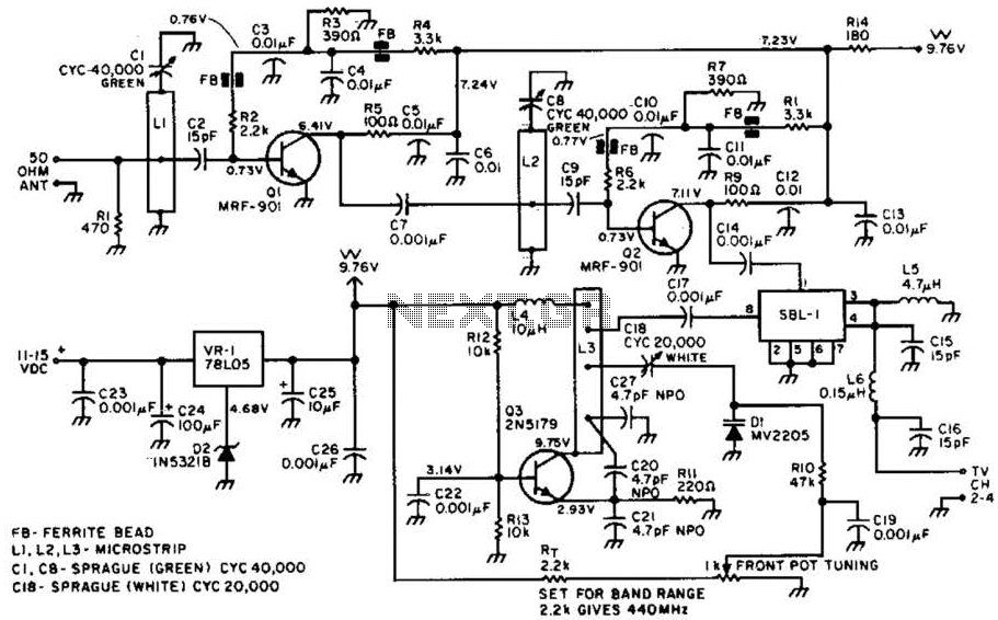
Most ATV (Amateur Television) transmitters operate using a Double Sideband (DSB) signal, while commercial television stations utilize a Vestigial Sideband (VSB) signal. This distinction is leveraged in this converter to utilize the lower sideband, thereby reducing interference from repeaters...
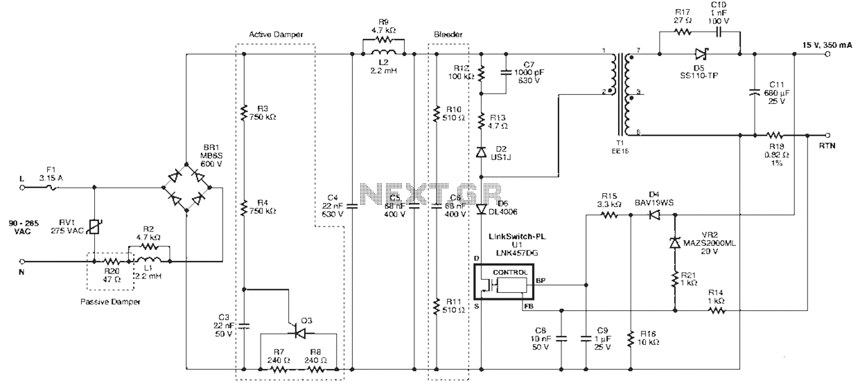
Power Integrations' DER322 reference design employs the LinkSwitch-PL family of LNK460VG devices. This design represents the industry's first alternative 100W A19 incandescent LED driver utilizing a single-layer PCB. It is characterized by low cost, minimal component count, and compact...
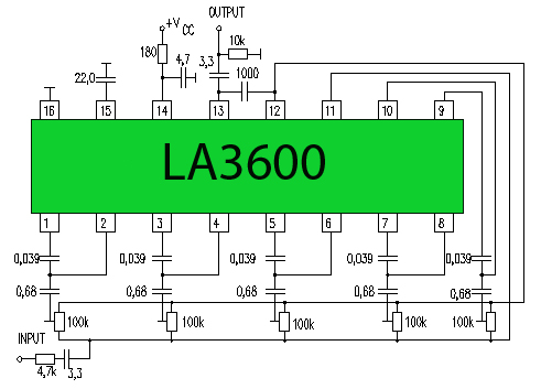
One type of tone regulator is the audio graphic equalizer, which can be categorized into two types: the audio graphic equalizer bar and the parametric equalizer. This article focuses on the bar type, specifically a 5-channel equalizer utilizing the...
To complement the 60 Watt MOSFET audio amplifier, a high-quality preamplifier design was necessary. A discrete component topology, utilizing +24V and -24V supply rails, was selected, minimizing the transistor count while ensuring low noise, very low distortion, and a...
To avoid excess ripple output on a power supply feeding a heavy load, usually a large value capacitor is chosen following the rectifier. In this circuit, C1 is only a 470uF capacitor. The gyrator principle uses the effect that...
Controlling household electrical gadgets or any electrical equipment remotely can be enjoyable. While using a remote to control devices like a TV or DVD player is a common experience, managing other domestic appliances such as water pumps and lights...