
Electronic Thermostat Circuit

The described circuit employs an IN4148 diode, which is characterized by its negative temperature coefficient, making it suitable for temperature sensing applications. The constant current source formed by transistors Q1 and Q2 ensures that the current flowing through the diode remains stable, allowing for accurate temperature readings. The output voltage from the diode, which varies with temperature, is amplified by the DC amplifiers ICl-a and ICl-b. The temperature reference voltage supplied by ICl-c is critical for establishing a baseline against which the temperature sensor's output can be compared.
ICl-d, functioning as a comparator, compares the amplified voltage from the temperature sensor against the reference voltage. The variable hysteresis implemented in the comparator helps to prevent oscillations in the output, ensuring stable operation when the temperature approaches the setpoint. The resistors R14, R15, and R16 are integral to setting the thresholds for the thermostat, allowing for customization based on the specific temperature range required for the application.
The relay driver Q3, utilizing a 2N3904 transistor, is responsible for activating the relay, which can control larger loads. It is essential that the relay is rated to handle the current requirements of the load it controls. Alternatively, for applications requiring electrical isolation and protection, an optoisolator paired with a triac can be employed, providing a robust solution for interfacing with high-power loads while maintaining safety and circuit integrity. This circuit design is particularly useful in temperature control systems, such as thermostats, where precise temperature regulation is necessary. A diode, such as a IN4148, has a typical -2m V/C temperature coefficient at a 1 mA diode current. Ql and Q2 form a constant current source. D1 is the temperature sensor. ICl-a and -b are dc amplifiers, with ICl-c a temperature reference voltage supply. ICl-d is a comparator with variable hysteresis. R14, R15, and R16 are chosen depending on the thermostat range desired. Q3 is a relay driver (2N3904). The relay used should handle the load current or an optoisolator triac combination can be used.
Related Circuits
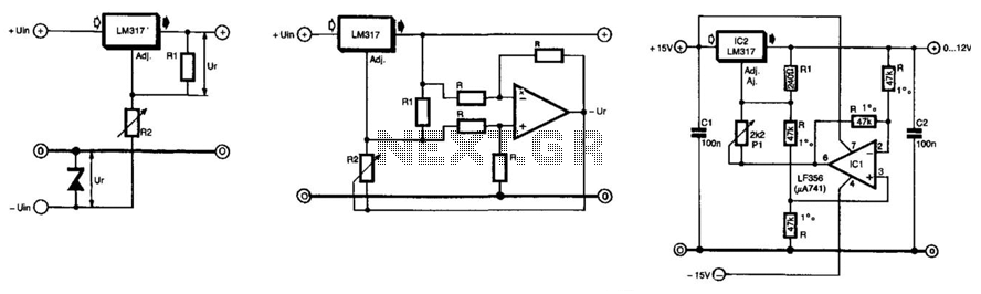
The unique feature of this regulator is that the output voltage can be adjusted down to 0 V. The regulation is provided by an integrated regulator type LM317. Typically, in supplies that can be adjusted to 0 V, this...

In electronic technology, the triode utilizes a variety of general components and parts. The parameters of the triode and numerous electrical parametric measurement schemes are closely related to measurement results. Therefore, in electronic design, the base pin, typological judgment,...
When the water level is below the steel rods, there is no contact between the metal can and the rods, which are supported by a small insulated wooden board. The circuit built around IC1 draws no current, resulting in...

The Dish Network 322 Satellite Receiver enables television viewing of two distinct programs in two separate locations. This is a schematic block diagram illustrating an exemplary circuit logic diagram. The receiver is capable of predicting the elevation angle for...

Figure 4-33 illustrates a circuit configuration that includes a common amplifier along with analog inductive circuits. In this setup, the transistor in the analog inductive circuit is utilized, and an increase in the bias resistor enhances circuit stability. A...

In some buildings, there is a need for effective security measures. An example of this is the door knock alarm, which is a simple design intended for basic home security. This circuit utilizes a piezoelectric sensor to detect knocking...