
metronome

The 555 timer is a versatile integrated circuit widely used in timer, pulse generation, and oscillator applications. In astable mode, it operates as an oscillator without requiring any external triggering. The frequency and duty cycle of the output waveform can be adjusted by varying the resistance and capacitance values in the circuit.
In this particular configuration, the 250K potentiometer (VR1) is connected between the discharge pin (Pin 7) and the threshold pin (Pin 6) of the 555 timer. The wiper of the potentiometer is connected to the timing capacitor (22.5 µF), which is also connected to ground. The capacitor charges and discharges through the resistive path provided by the potentiometer and a fixed resistor, if present, thereby controlling the frequency of the oscillation.
The output square wave at Pin 3 can be connected to various loads, such as a small speaker or a buzzer, to produce sound. The 22.5 µF electrolytic capacitor smooths the output waveform, which helps in achieving a more pleasant sound quality by filtering out high-frequency components.
It is essential to ensure that the capacitor is correctly polarized, as electrolytic capacitors are sensitive to reverse voltage. The circuit's design allows for easy adjustment of the sound frequency, making it suitable for applications where sound generation is required, such as alarms, timers, or simple musical devices. Proper power supply decoupling should also be considered to enhance the stability of the 555 timer's operation.This circuit uses the 555 timer in an Astable operating mode and generates a continuous output via Pin 3 in the form of a square wave. This is then passed through the 22 ½F electrolytic capacitor to create a smooth oscillation which then creates the `toc-toc` sound.
The speed of the output is controlled by the 250K Potentiometer (VR1). 🔗 External reference
Related Circuits
The metronome circuit has been assembled multiple times without success. Two manufacturers of the 555 timer, ON Semiconductor and National Semiconductor, provide circuit designs that differ from the original. In their designs, pins 2, 6, and 7 are not...
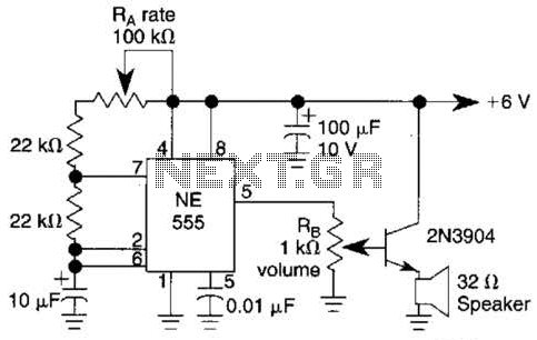
Ra sets the rate while RH sets the volume of clocks in the speaker. The 555 is configured as a low frequency oscillator. The circuit is powered by a 6 V battery. The circuit utilizes a 555 timer IC configured...

This is a simple circuit utilizing the NE555 integrated circuit (IC) designed to generate metronomes. Such a circuit is particularly beneficial for music learners. The configuration operates as an astable multivibrator centered around the NE555. The output frequency is...
This is a metronome circuit that features a mechanical sound character. A metronome with a mechanical sound character enhances the experience and enjoyment of musical practice. The metronome circuit is designed to produce rhythmic sounds that assist musicians in maintaining...
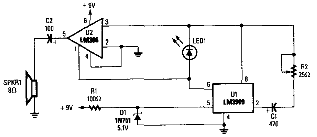
The LM3909 is configured such that the frequency of oscillation relies on a single RC timing circuit, which includes capacitor C1 and resistor R2. LED1 discharges capacitor C1, and the resulting pulse is directed to both pin 3 and...
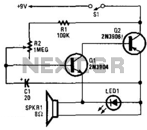
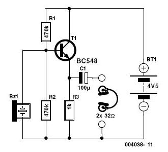
Two complementary transistors create a basic oscillator with a frequency range of approximately 0.5 to several Hz. This circuit serves as a metronome, timer, or pacer for exercise equipment. The oscillator circuit utilizes a pair of complementary transistors, typically one...