
Metronome generator circuit

The NE555 timer is a versatile component widely used in various timing applications. In this metronome circuit, it functions in astable mode, continuously oscillating between high and low states to produce a square wave output. The frequency of this output is crucial for generating a consistent beat, which is essential for practice in music.
The resistors R1 and R2, along with the capacitor C1, set the timing interval of the oscillation. The frequency (f) of the output signal can be calculated using the formula:
\[ f = \frac{1.44}{(R1 + 2R2) \cdot C1} \]
Where:
- R1 is connected between the discharge pin (pin 7) and the supply voltage (Vcc).
- R2 is connected from the discharge pin (pin 7) to the threshold pin (pin 6).
- C1 is connected from the threshold pin (pin 6) to ground.
In this configuration, the output frequency can be adjusted by varying the values of R1, R2, and C1, allowing users to set the metronome to their desired tempo.
Additionally, a speaker or piezo buzzer can be connected to the output pin (pin 3) of the NE555 to convert the electrical signal into audible sound. A simple low-pass filter may be integrated to smooth out the signal if necessary, enhancing the sound quality.
This metronome circuit can be powered by a standard DC power supply, typically in the range of 5V to 15V, making it suitable for various applications. The simplicity of the circuit and the low cost of components make it an excellent project for beginners in electronics and music education.Here is a simple circuit using IC NE555 that can be used to generate metronomes. Such a circuit is very useful to those who learns music. The circuit is nothing but an astable multivibrator wired around NE555. The components R1, R2&C1 determines the output frequency. 🔗 External reference
Related Circuits
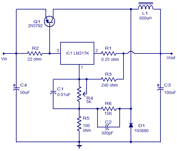
This circuit illustrates a 3A Switching Regulator Circuit based on the LM317K integrated circuit. It is designed to be simple and cost-effective. The 3A Switching Regulator Circuit utilizing the LM317K IC serves as a versatile voltage regulation solution, capable of...
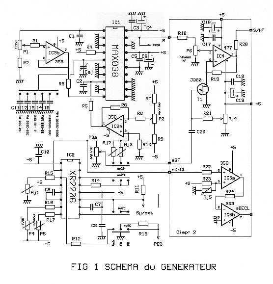
The GHF1 is a small generator covering the HF and LF band from 30 Hz to 30 MHz in 6 ranges. The sinusoidal signal obtained can be amplitude modulated (AM) or frequency (FM). The GHF1 also has a sweep...
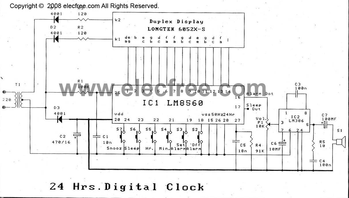
The digital time clock circuit is of great interest to electronic amateurs. The most popular clock ICs include the LM8361 and MM5387. Unfortunately, these ICs... The digital time clock circuit serves as an essential component for various electronic applications, providing...
The two circuits below illustrate using the 555 timer to close a relay for a predetermined amount of time by pressing a momentary N/O push button. The circuit on the left can be used for long time periods where...
Today, nearly all computers are equipped with logic blocks designed to implement a USB port. In practice, a USB port can deliver over 100 mA of continuous current at 5V to the peripherals connected to the bus. This capability...
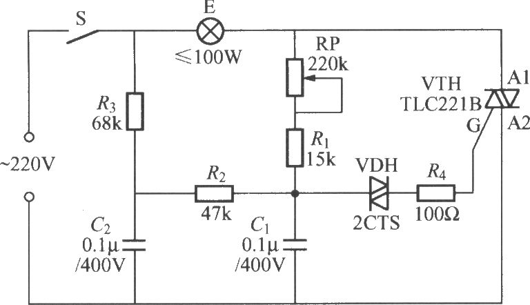
To address the lag and light transition issues, a Triac dimming light circuit featuring a dual time constant can be employed. This circuit enhances the resistor-capacitor network formed by R3 and C2. The reduced charge on capacitor C1 can...