
micro power am broadcast transmitter

The circuit operates by leveraging the characteristics of the 74HC14, which features hysteresis in its input thresholds, allowing for stable oscillation even in the presence of noise. The inverter generates a square wave output that alternates between high and low states, which is then used to modulate the base of the small signal transistor. This transistor, configured in a class C arrangement, operates efficiently by conducting for less than half of the input cycle, making it suitable for RF amplification applications.
In the fixed frequency configuration, the crystal oscillator provides a stable frequency reference, ensuring precise and consistent operation. When the circuit is set to VFO mode, the combination of the capacitor and resistor allows for frequency adjustments. The 100pF capacitor plays a crucial role in determining the oscillation frequency, which can be varied by changing the resistor value in the RC network.
The output of the small signal transistor can be connected to an antenna or further amplification stages, depending on the application. Proper biasing of the transistor is essential to ensure optimal performance and to prevent distortion in the amplified signal. Additionally, bypass capacitors may be included to filter out any high-frequency noise from the power supply, enhancing the overall stability and performance of the circuit.
Overall, this circuit design provides a versatile solution for generating square wave signals suitable for various applications in electronics, particularly in RF transmission and signal modulation systems.In this circuit, a 74HC14 hex Schmitt trigger inverter is used as a square wave oscillator to drive a small signal transistor in a class C amplifier configuration. The oscillator frequency can be either fixed by a crystal or made adjustable (VFO) with a capacitor/resistor combination.
A 100pF capacitor is used in place of the crystal for VFO operation.. 🔗 External reference
Related Circuits
Soundblaster soundcard series (SB16, SB32, AWE32 and AWE64) have all a microphone input designed to be used with the electret microphones which come with the soundcard package (some packages) or with separate microphone designed to be used with SoundBlaster...

This application note discusses the use of SEPIC power modules to supply the necessary power for driving high-brightness LED arrays. These arrays serve as display backlights and necessitate a wide dimming range. The SEPIC configuration offers an efficient and...
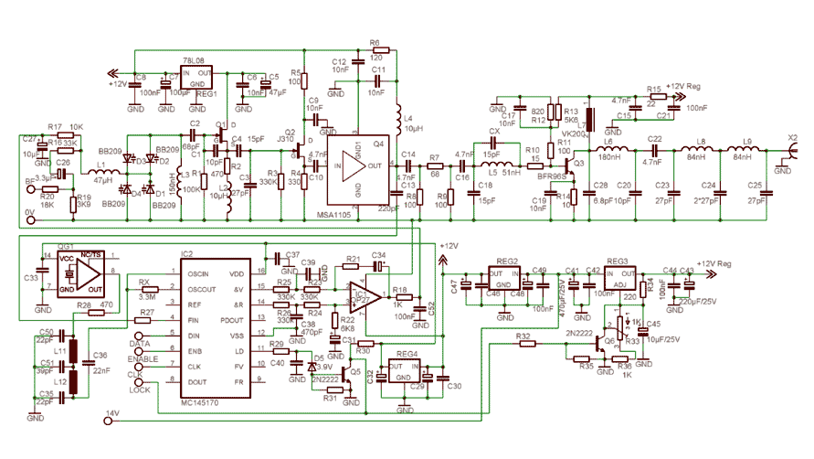
In order to simplify the transmitter design, we've used the new pll circuit from Motorola: the MC145170. This PLL includes the prescaler and a serial standard bus called SPI. We advise to use the P2 version that fixes some...
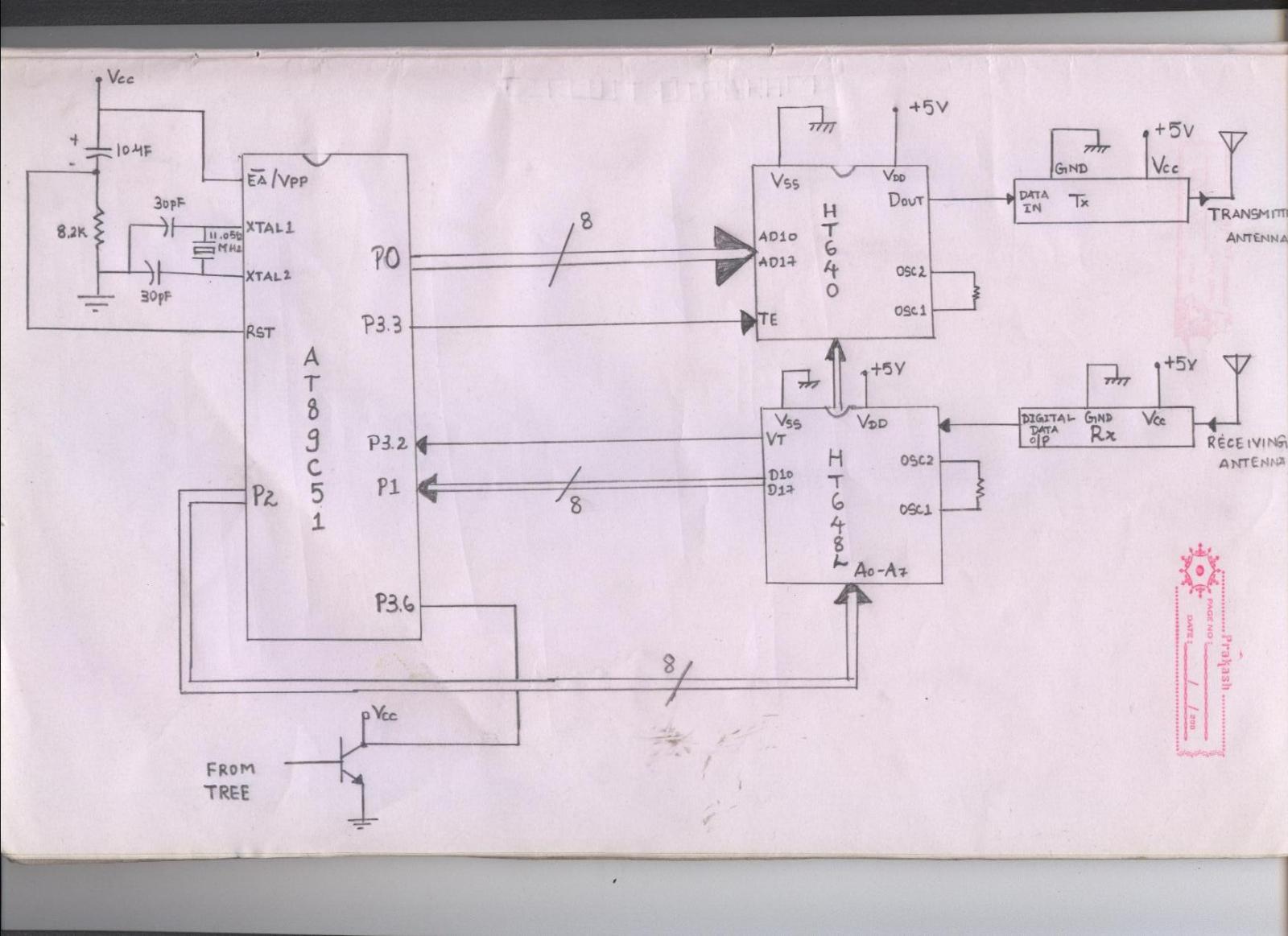
The issue arises when connecting the 8051 microcontroller to the HT640 encoder; the data transmitted is not received by the receiver. However, when the 8051 connections are removed, the transmission functions correctly. This indicates that manual RF communication works...
The following circuit illustrates the connection of the Devantech SRF04 Ultrasonic Sensor to the SV203 powered PPRK Circuit Diagram. This circuit is based on the Devantech SRF04 sensor and features a minimum initiation time of 10 milliseconds for the...
FM Beacon Broadcast Transmitter (88-108 MHz). This circuit will transmit a continuous audio tone on the FM broadcast band (88-108 MHz), which could be used for remote control or security purposes. The FM Beacon Broadcast Transmitter operates within the frequency...