
Outdoor Garden Solar Lights circuit

The circuit operates by harnessing solar energy to power LED lights in garden settings. The solar panel collects sunlight, converting it into electrical energy, which is then used to charge the SLA battery during the day. The diode (D9) is crucial for preventing reverse current flow, ensuring that the battery does not discharge back into the solar panel at night. The current limiting resistor (R10) is employed to regulate the charging current to protect the battery from overcharging.
The LDR plays a pivotal role in the automatic operation of the garden lights. It senses the ambient light levels; when the sunlight diminishes at dusk, the resistance of the LDR increases, triggering the base of transistor T1. This action allows transistor T1 to conduct, thereby activating the LED lights connected to the circuit. This automatic switching feature ensures that the lights turn on only when needed, providing an energy-efficient solution for outdoor lighting.
In addition to the components already mentioned, the circuit may also include a few capacitors for stabilization and noise filtering, enhancing the reliability of the system. Proper placement of the solar panel is essential to maximize sunlight exposure throughout the day. The entire setup can be housed in a weatherproof enclosure to protect the electronic components from the elements, ensuring longevity and durability of the garden lighting system.This Outdoor LED Solar Garden Lights project is a hobby circuit of an automatic garden light using a LDR and 6V/5W solar panel. During day time, the internal rechargeable 6 Volt SLA battery receives charging current from the connected solar panel through polariy protection diode D9 and current limiting resistor R10.
If ambient light is normal, transistor T1.. 🔗 External reference
Related Circuits
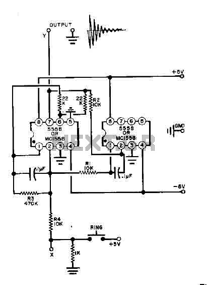
This simple bell circuit utilizes two 555 timers. The frequency is regulated by capacitors that should maintain nearly identical values for optimal performance. Fine-tuning is achieved using resistors R1 and R2. Additionally, the decay time is managed by resistor...
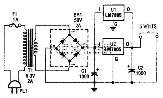
This DC supply is excellent for operating battery-powered antique radios, as it is designed to prevent damage to the tube filaments. The circuit is useful for powering the filaments of 00-A, 01-A, 112A, and 71A tubes, which require 5V...
It was observed that balls were becoming lodged in the ball trough, failing to load into an upkicker or not resting correctly on the trough ball microswitches or optos, which caused the machine to register a missing ball. Initially,...
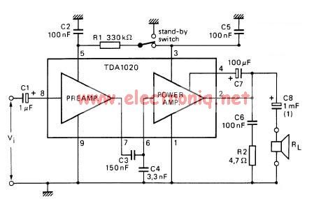
The TDA1020 is a monolithic integrated 12 W audio amplifier housed in a 9-lead single in-line (SIL) plastic package. Although it is designed primarily for car audio applications, it can also be utilized in various other audio applications. The TDA1020...
A USBI2C can be utilized with each sensor, allowing for a configuration of four sensors at a cost of £120. The SRF02 operates on the I2C bus, which should not be extended beyond approximately 2 meters. The proposed solution...
The circuit is designed to provide protection to a DIY switching power supply for car amplifiers by shutting down under any or all of the three modes of protection (over voltage, under voltage and over temperature) with minimal components. The...