
Microchip Tutorial

The OSCCON register is a critical component in microcontroller applications, particularly in configuring the clock speed for optimal performance. The default operating frequency of 31 kHz may not be suitable for applications requiring higher processing speeds, hence the adjustment to 8 MHz. This adjustment allows for faster execution of instructions, which is vital in time-sensitive applications.
The TRISB register, which stands for Tri-State Register B, is used to control the direction of the pins on Port B of the microcontroller. Setting a bit in the TRISB register to '1' configures the corresponding pin as an input, while setting it to '0' configures it as an output. This functionality is essential for interfacing with various peripherals and controlling external devices.
To ensure proper functionality, the microcontroller must be correctly placed in the ZIF socket, and the external 9V supply must be connected to the circuit. Failure to do so may lead to complications, such as receiving an invalid device ID or the Vdd voltage being insufficient for operation.
The "Reset and connect to ICD" button is part of the Integrated Development Environment (IDE) used for programming and debugging the microcontroller. This toolbar typically appears within the MPLAB IDE interface, facilitating the connection to the In-Circuit Debugger (ICD) for real-time debugging and programming.
The internal clock frequency, denoted as Fosc, is crucial for the operation of timers within the microcontroller. The P18F1320's architecture allows for efficient instruction processing, with a clear relationship between the oscillator frequency and the execution speed of instructions. The setup of timers as either 8-bit or 16-bit allows for flexibility in counting, accommodating various application requirements.
The described circuit, which activates an LED in response to a magnetic field detected by a Hall effect sensor, exemplifies a practical application of microcontroller technology. The ability of the PIC microcontroller to read analog voltages through the A/D converter enhances its capability to interact with analog sensors, enabling a wide range of applications in automation and control systems.Look for the OSCCON register in the data sheet (as of this edit, page 19). This register, among other things, controls the speed of the internal clock. Upon startup, the processor runs at 31 kHz (way too slow. ) Using OSCCON, we can increase the speed to 8MHz. on reset all your pins are set to input (TRISB is set to high). So set TRISB low to do ou tput on a pin. *Can you add a breif description of what TRISB means Like you did for OSCCON above * Put the chip in the ZIF socket. Also make sure the hockey puck has the external 9V supply attached to it, otherwise the following steps will give you an error message about invalid device ID, and Vdd will be 0V instead of 5V.
*Where is the 9V supply attached to * Then, on toolbar that appears: "Reset and connect to ICD" button *Where does this toolbar appear And what do you do with it Are we supposed to go into the MPLAB ICD 2 Setup Wizard * The internal PIC clock runs at whatever speed we set it to (via OSCCON register)-this frequency is denoted Fosc. The timers will tick one tick per instruction cycle. In the P18F1320 one instruction is executed every 4 clock ticks, so if our oscillator is at 8MHz (Fosc = 8MHz) then instructions will be executed at 2MHz.
So, the timers will increment at 2MHz. If the timer is set up as 8-bit, the number you count up to can only go up to 256. If it is set up as 16-bit, you can count up to 65, 536. The subtraction will always work out correctly (even if the timer wraps around, which it will) if you cast the subtraction as an unsigned char (for 8-bit) or unsigned int (for 16-bit). This circuit turns on the LED when a magnet is held close to the Hall effect sensor, with either end (North or South) towards the hall effect sensor.
The PIC reads in the analog voltage from the Hall effect sensor using the A/D converter. 🔗 External reference
Related Circuits
The most essential schematic to understand for any robot, whether for beginners or advanced users, is the circuit designed to control the robot's power source. It is inadequate to connect a battery directly to all components and expect proper...
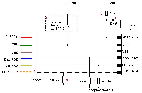
Microchip does not recommend any specific circuit for In-Circuit Serial Programming (ICSP). Various diagrams exist for different tools, such as Pro Mate and PICKit2, which feature similar circuitry with minor variations. Some schematics may suggest resistor values that are...
Electronics tutorial on the passive band pass filter circuit, which includes the passive RC band pass filter's first-order frequency response and Bode plot. The passive band pass filter circuit is a fundamental electronic component that allows signals within a specific...
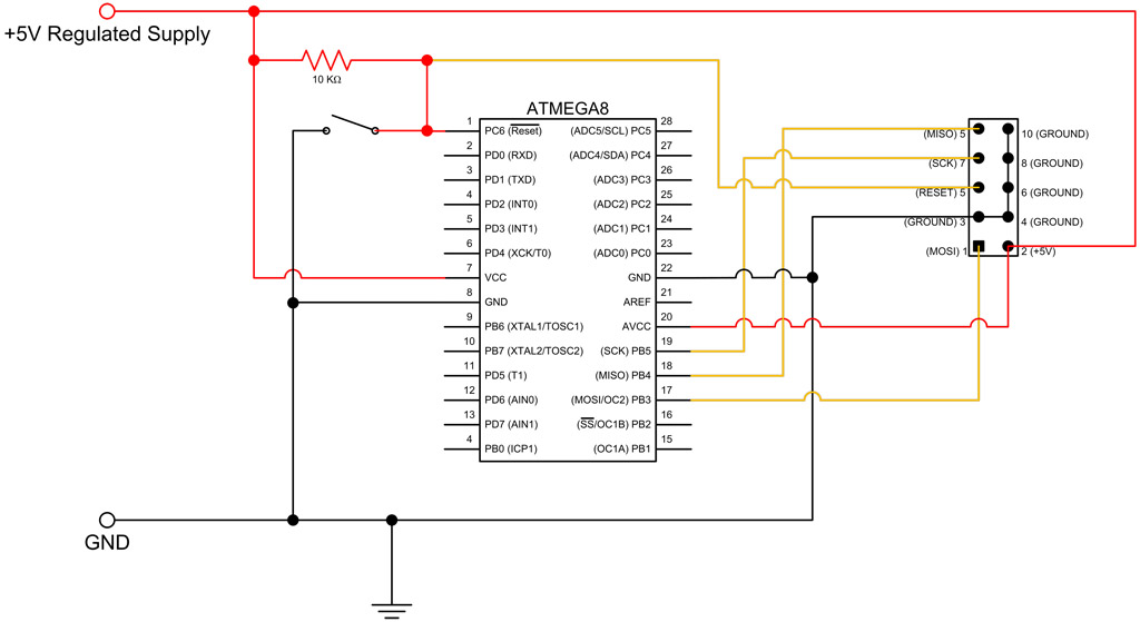
This tutorial continues from the ATmega8 Breadboard Circuit Part 1, where a small power supply was built on a breadboard. In this part, the ATmega8 microcontroller will be added along with an interface for programming. The first step is...
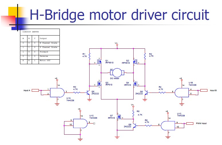
An H-bridge motor driver circuit is designed to control a DC motor. By using a low signal, such as a 5-volt signal, the circuit enables the program to manage the motor, which operates on a higher power supply. The H-bridge...
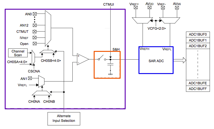
The PIC32's Analog to Digital Converter (ADC) can be challenging to configure for first-time users. The extensive range of configuration options available for the PIC peripherals can be overwhelming. This tutorial aims to assist users in navigating these complexities. The...