
Robot Tutorials power regulation

The power regulation circuit is fundamental for ensuring the stability and reliability of robotic systems. It typically comprises several key components: a power source (battery), a voltage regulator or switching regulator, and various connectors and capacitors that facilitate power distribution to different modules.
The power source must be selected based on the total voltage and current requirements of all components in the robot. The voltage regulator or switching regulator serves to maintain a steady output voltage, regardless of fluctuations in the input voltage, thereby protecting sensitive components from damage.
Capacitors are often included in the design to smooth out voltage spikes and dips, providing additional stability to the power supply. The selection of capacitors should be based on their voltage rating and capacitance value, which must be compatible with the power requirements of the circuit.
Additionally, it is essential to consider the thermal management of the voltage regulation components. Heat sinks or active cooling methods may be necessary to dissipate heat generated during operation, particularly in high-current applications.
Wiring and layout are equally important in the design of the power regulation circuit. Proper routing of power lines and minimizing the length of connections can reduce resistance and prevent voltage drops, ensuring that all components receive adequate power.
In summary, a well-designed power regulation circuit is crucial for the successful operation of robotic systems, ensuring that all components function reliably and efficiently. It is imperative to assess the specific power requirements of each component and select appropriate regulators and supporting circuitry to achieve optimal performance.The most important schematic to know, one that is almost always required for every robot whether you`re a beginner or advanced, is a circuit to control your robots` power source. You cannot just hook up a battery directly to everything and expect it to work. Instead, there are three things that your power regulation circuit must do - regulate at a set voltage, supply a minimum required amount of required power at all times, and allow for additional special features/requirements of your application: For efficiency, optimally it would be best to use a power source closest (yet slightly above) the desired voltage input required. However this is rarely easy or even feasible. For a start, different electronics require different voltages. A microcontroller will require 5V, your motors perhaps 12V, a voltage amplifier perhaps both 20V and -20V.
Batteries are never at a constant voltage. A 6V battery will be at around 7V when fully charged, and can drop to 3-4V when drained. This below image shows how a typical battery voltage changes over time. Microcontrollers (and especially sensors) are sensitive to the input voltage. Change the voltage, and funny (bad) things happen. To correct for this, you need to use an IC called a voltage regulator. What a voltage regulator does is take any input voltage and outputs a regulated voltage. So if your battery is at 7V, then a 5V regulator will output 5V and a lot of heat to dissipate the unused energy. Since microcontrollers and sensors typically do not consume that much current, the wasted energy isnt that much.
But for motors, this can be a huge problem. You do not want to over voltage them, but to regulate the voltage is a huge waste of energy. To correct for this, what you instead use is a switching regulator. They act just like a voltage regulator in terms of output, but are much much more efficient. If you need to regulate a 12V battery input for say a bunch of 6V servos, a switching regulator is the way to go. If your current voltage regulator overheats (melts, explodes, or requires ginormous heatsinks), then you should use a switching regulator.
At the time of this writing, the best switching regulator I have found can be bought at dimensionengineering. com. The sum required power of all your robot components needs to be below the amount your power circuit can supply.
If power drops even for a fraction of a second below what your robot requires, things like the microcontroller could reset, or sensors would give bad readings, or motors wont work very well. 🔗 External reference
Related Circuits
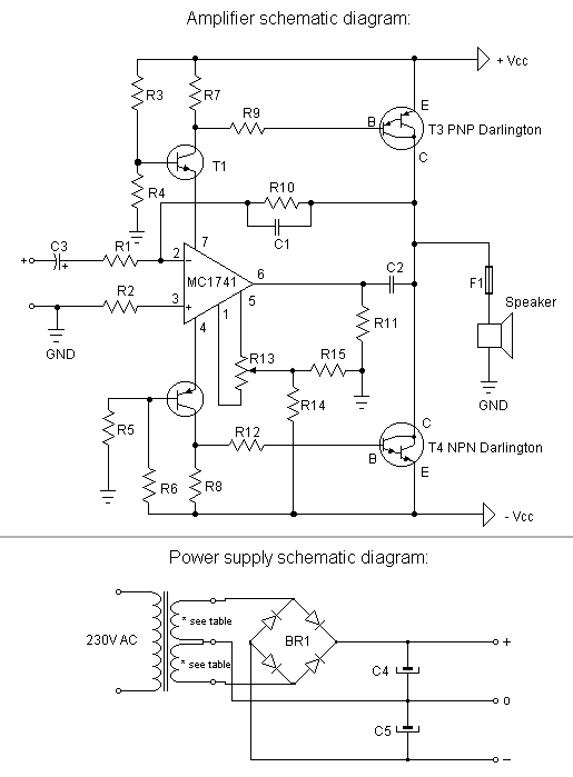
This is a very simple, low-cost, Hi-Fi quality power amplifier. It can be built in five different configurations, as shown in the table, ranging from 20 W to 80 W RMS. The Hi-Fi quality power amplifier circuit is designed to...
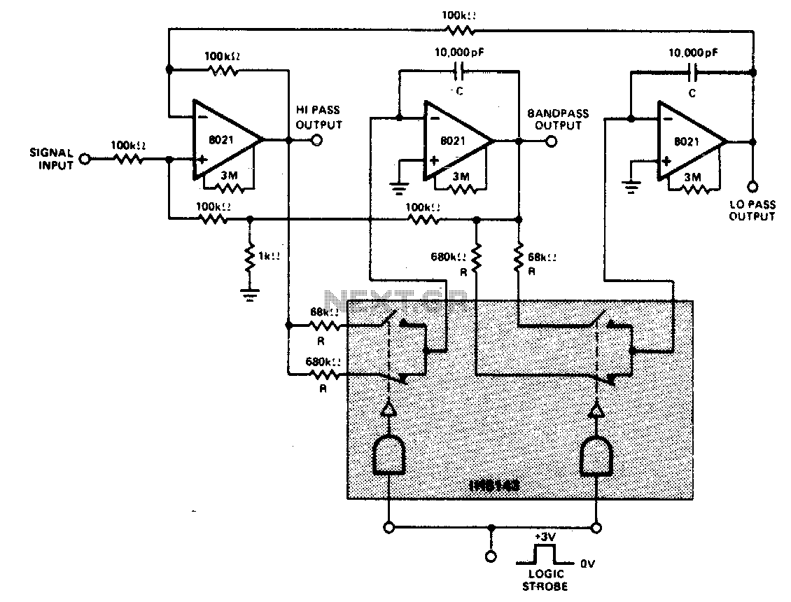
A constant gain, constant Q, variable frequency filter that provides simultaneous low-pass, bandpass, and high-pass outputs. With the specified component values, the center frequency will be 235 Hz and 23 Hz for high and low logic inputs, respectively, with...
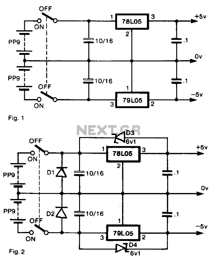
To generate regulated ±5-V supplies from a pair of dry batteries, the circuit shown in Fig. 1 is commonly utilized. To protect against inadvertent reverse connection of a battery, a diode in series with each battery would create an...
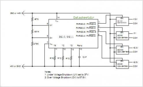
The PS10 saves board space, improves accuracy, eliminates optocouplers or level shifts, and reduces overall component count by combining four programmable timers, input under-voltage (UV) and over-voltage (OV) supervisors, a programmable power-on reset (POR), and four 90V open drain...
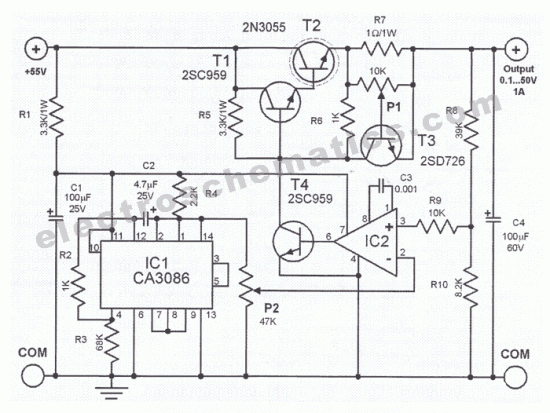
0.1V to 50V Variable Power Supply Circuit Diagram. Features: the lowest current limit is 0.6 ampere, opamp CA3130 compares the reference voltage. The variable power supply circuit is designed to provide an adjustable output voltage ranging from 0.1V to 50V,...
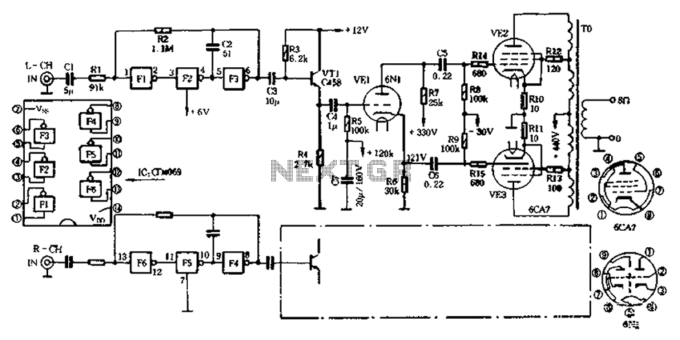
The CD4069 unit structure depicted in Figure 2-5 (a) consists of two abutment surfaces incorporated into a CMOSFET configuration. The input-output characteristics are illustrated in Figure 2-5 (b). Due to its superior unit switching curve, the CD4069 can be...