
Photo Meter Assesses Ambient Light Schematic

The described circuit leverages the properties of PN-junction diodes and LEDs for ambient light detection and color evaluation. The fundamental operation begins with the reverse biasing of the LED, which allows it to function as a photodiode. The small photocurrent generated by the LED in response to ambient light is critical for the circuit's operation. The choice of three different LEDs allows for a comparative analysis of their sensitivity to various wavelengths of light, enabling the circuit to discern different colors based on the varying responses of the LEDs.
The use of transistors Q1 and Q2 for signal amplification is essential for enhancing the weak signals generated by the LEDs. The first transistor (Q1) amplifies the photocurrent, and its collector current is split into two paths: one through the potentiometer R4 for gain calibration, and the other to the base of the second transistor (Q2) for further amplification. The bridge circuit formed by D1A and D1B provides a means to measure the output imbalance caused by Q2's collector current, which is indicative of the light intensity and color detected by the LEDs.
The inclusion of variable resistors R4 and R5 allows for fine-tuning of the circuit's sensitivity and calibration, making it adaptable to different lighting conditions and requirements. The circuit's simplicity and low-cost components make it an accessible option for applications in ambient light sensing and color detection, suitable for educational purposes or basic environmental monitoring. The practical approach of using off-the-shelf LEDs, combined with straightforward amplification and measurement techniques, results in a functional device capable of providing valuable insights into ambient lighting conditions.Most PN-junction diodes can be used as photodiodes. While not optimized for this application, they do work. When the diode is reverse biased, it will produce a small photovoltaic output as the light level is increased. LEDs are particularly suited for this task because their housings are transparent. You can construct a simple circuit that will assess the condition of ambient lighting and, because many LEDs` packages are tinted to enhance their emitted color, may even yield a reasonable evaluation of the detected color. The results are not as effective as those obtained using a high-quality optical filter, which typically has narrow bandpass characteristics, but they can be quite acceptable.
Though the design described here does not produce the accuracy of designs with laboratory-grade photodetectors and transimpedance amplifiers, it can be quickly assembled and will produce usable results at a low cost. Three LEDs are used; experimentation will indicate which device has the best sensitivity to which color (Figure 1).
The ambient light falling on the LEDs causes some current flow ”typically in the range of 10 to 100 nA ”through each LED, depending on the applied illumination level. This current flows through the base of a transistor, Q1, and is amplified. Q1`s collector current then splits between potentiometer R4, which acts as a first-stage gain calibration, and the base of Q2.
Q2 provides further amplification and drives the left side of a bridge circuit (D1A and D1B). Note that R2/D1 and R3/D2 form a balanced bridge. Q2`s collector current provides a slight imbalance to the bridge. The meter, M, measures this imbalance. R5 adjusts the sensitivity of the meter. Set R4 and R5 such that the meter has an appropriate deflection. R4 is useful for selecting the quiescent point; R5 is useful for adjusting the sensitivity. Before building the circuit, check whether the LEDs can be used as photo sensors. To determine whether a given LED is a good photodiode, check the voltage across the LED using a common digital multimeter set to its most sensitive range ”typically 200 mV. Typical output voltage should be approximately 0. 3 to 1 mV with typical office illumination. 🔗 External reference
Related Circuits
This document tells about one of my experiments with semiconductor laser modules. I bought one semiconductor laser for all kinds of experiments. This TIM202 module is a small (38x14x14 mm) semiconductor laser module, similar to those types used in...
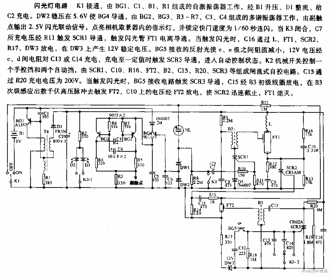
The camera flashlight circuit activates when switch K1 is engaged. This triggers a self-oscillating circuit consisting of BG1, capacitor C1, battery B1, and resistor R1. Once operational, the circuit boosts the voltage through B1 and rectifies it using diode...

This circuit employs a FET as a DC amplifier within a bridge configuration. Resistor R4 is adjusted for meter nulling with switch J1 short-circuited. Any surplus 50-mA meter can be utilized in this circuit. RFC1 represents a suitable RF...

A radio control circuit designed for controlling small motors, similar to a car radio remote control toy, offers seven functions: forward, backward, left, right, left behind, right behind, and stop. The circuit requires a 27.9 megahertz frequency and a...

The circuit is intentionally designed using older type transistors to achieve harmonic distortion and to mitigate the challenges of sourcing high-quality components. The amplifiers can be easily powered by a plug-in wall transformer rated at 12V. When SW1 is...
This circuit is designed to indicate when a plant requires watering. An LED blinks at a low frequency when the soil in the flower pot is excessively dry, turning off as the moisture level rises. The sensitivity of the...