
microcontroller Why this transistor logic as switch is not working

The described circuit modification involves using a transistor as a switch to control the operation of an RC car via a BeagleBone Black's I/O pins. The remote control's switch wires are connected to the collector of the transistor, while the emitter is connected to ground. The base of the transistor is meant to receive a control signal from the BeagleBone, which would turn the transistor on and allow current to flow from the collector to the emitter, thereby completing the circuit and signaling the car.
The issue arises when the circuit remains closed without a base voltage being applied. This behavior indicates that the transistor may be in a state of leakage or that it is inadvertently biased into conduction due to the circuit configuration. To troubleshoot this, it is important to ensure that the base resistor is appropriately calculated to limit the base current to a safe level for the transistor while ensuring it turns on fully when activated.
The BeagleBone I/O pin, when set high, should provide sufficient voltage to the base of the transistor. The resistor connected to the base should be calculated using Ohm's Law, considering the transistor's current gain (beta) and the desired collector current. The formula for the base resistor (Rb) can be expressed as:
\[ Rb = \frac{(V_{be} - V_{base})}{I_b} \]
Where \( V_{be} \) is the base-emitter voltage (typically around 0.7V for silicon transistors), \( V_{base} \) is the BeagleBone output voltage (3.3V), and \( I_b \) is the base current, which can be derived from the desired collector current divided by the transistor's current gain.
Additionally, it is essential to verify that the transistor is not damaged and that the connections are secure. A multimeter can be used to check for unexpected continuity between the collector and emitter when the base is not energized. If leakage is detected, replacing the transistor may be necessary.
In summary, the circuit design should allow for the BeagleBone to control the RC car's remote signals effectively. Ensuring correct resistor values and verifying the integrity of the components will aid in achieving the desired functionality.I opened remote of a RC car and extended wires out of backward, forward, left and right switches. So when I ground anyone of then the circuit completes andit sends signal to the car. I wanted to close the circuit using one of the I/O pins of BeagleBone Black. The output voltage on these I/O pins is about 3. 3V. I found out that I can use transistor as a switch but after a putting all the things together the circuit remains closed even without supplying base voltage to transistor as shown in the diagram. I am also showing the calculations used by me to get the resistances required at the Base terminal. Transistors can be used a switch when you supply base current. The circuit remains closed without supplying any base voltage. In short the collector emitter terminal are closing the circuit from one of the remote pins with ground.
I wanted the circuit to close when I turn one of the pins on the BeagleBone high. I am doing something wrong but I don`t know what I am doing wrong. Any suggestions in the right direction would be greatly appreciated. 🔗 External reference
Related Circuits

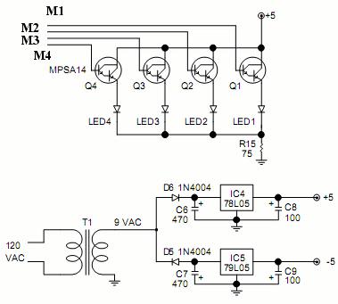
This logic probe features four channels and employs two quad comparator integrated circuits to drive four bicolor LEDs. The SI and SIB pins are used to set the comparator trip levels for TTL and CMOS logic families. Resistors R6...
A video switcher circuit is required to display multiple sources on a single monitor. The circuit schematic below features the MAX454, which serves as the core component of this video switcher. The MAX454 is a video multiplexer-amplifier manufactured by...
A 100 second delayed turn ON relay RL1 switch, if plug power +12V in circuit. In Fig.2 see a two range 6-60 second and 1-10 minute auto turn off relay timer circuit, with 555. Part List R1=1 Mohms C4=100nF...
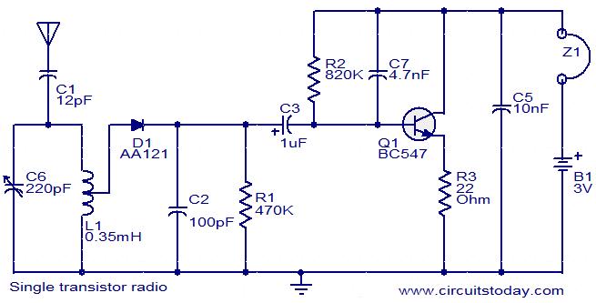
The circuit diagram of a simple radio that uses one transistor and a few other passive components. Component: Diode, Capacitor, Inductor, Resistor. The circuit design for a simple radio receiver typically incorporates a single transistor as the active amplification element,...

Three integrated circuits (ICs) are utilized to generate sounds. IC1 is a 555 timer configured as an astable multivibrator, producing clock pulses. The frequency of these clock pulses is adjustable via a trimmer potentiometer, P1. These clock pulses are...

This is a small circuit designed for use as a charging controller or voltage limiter. It is particularly useful for creating a solar charger. The assembly of the circuit allows for modifications according to personal preferences. The circuit is...