
Incect Robot circuit (PIC16F818)
")
The described circuit utilizes the PIC16F818 microcontroller, which is pivotal for controlling the operation of the device. The microcontroller is programmed to generate position pulses for two servos that facilitate both forward and backward walking sequences. The simplicity of the circuit design minimizes the need for additional components, leveraging the integrated features of the PIC16F818.
The internal Analog-to-Digital (A/D) converter of the microcontroller plays a crucial role in monitoring environmental parameters. It measures the room light level, providing feedback for the device's operational states. Additionally, it can assess battery condition and servo power draw, which indicates the mechanical loading on the servos. Although the software implementation for battery condition monitoring is not yet completed, the voltage across an LED serves as a proxy for the supply voltage (VCC) to the PIC. This method is effective due to the relatively constant voltage drop across the LED, allowing for an indirect measurement of the battery status—lower battery voltage results in a higher reading across the LED.
The operational cycle of the device is designed for energy efficiency. Upon powering up, the system measures the ambient light level and subsequently enters a low-power mode, where power is cut off to the servos, LED, and photo sensor. The microcontroller operates at a reduced clock frequency of 32 kHz during this low-power state. Approximately once every second, the microcontroller 'wakes up' to check the ambient light level. If a significant change is detected, the device executes a sequence of movements—advancing five steps forward and then five steps backward—before returning to its low-power state. This operational strategy balances responsiveness to environmental changes with energy conservation, making the device suitable for prolonged use.Very little extra circuitry is needed to do both forword and backword walking sequences along with a few other tricks. The PIC16F818 has a lot of features that work well in this situation. As you can see from the Schematic and Source Listing, position pulses for the 2 servos are generated dirctly from the PIC.
Also, the room light level, battery condition, and servo power draw (indicating mechanical loading) can be measured with the internal A/D. The battery condition (although not yet in the software) can be determined by reading voltage accross the LED.
Since this voltage is (somewhat) constant, reading it actually measures the VCC to the PIC, which is where it gets its reference voltage. A higher reading on the LED means the battery voltage is lower. In its present state, this device powers up and measures the room light level then goes into low power mode (no power to servos, LED, or photo sensor) at 32 khz internal clock. About once a second, it 'wakes up' and checks the light level. If it finds a significant change, it cycles five steps forward, five steps back, and then shuts back down.
🔗 External reference
Related Circuits
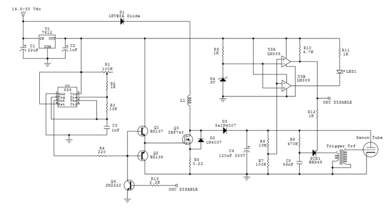
The circuit utilizes an IRF740 MOSFET, which has a maximum drain-source voltage (V_DS) rating of 400V. The avalanche voltage is calculated to be approximately 3520V, indicating that up to about 500V of inductive kickback voltage can develop in the...

This circuit connects in series with a home phone line and transmits phone conversations through the FM band whenever the telephone handset is picked up. The transmitted signal can be tuned by any FM receiver. The circuit includes an...
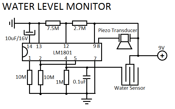
This simple water level sensor circuit monitors the presence of water in a specific location or container. The circuit activates an acoustic alarm when it detects water. The water level sensor circuit typically consists of several key components, including a...
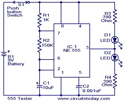
This schematic requires clarification. It is assumed that pin 2 is connected by a wire to pin 6, although this connection appears to be unclear. The circuit in question involves a schematic where pin 2 and pin 6 are interconnected....
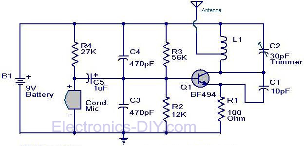
The circuit diagram of a simple FM transmitter utilizing a transistor is presented. While this design may not guarantee exceptional performance or range, it serves as a fundamental example. The circuit employs a general-purpose radio frequency transistor, the BF...

Frequency converter schematic, frequency to voltage converter schematic, frequency to voltage converter using TR, voltage to frequency converter application. A frequency converter is an essential electronic circuit that transforms frequency signals into corresponding voltage levels or vice versa. The frequency...