
Microfarad Counter

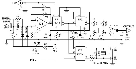
This capacitance measurement circuit operates on the principle of charging an unknown capacitor through a known resistor, allowing the time constant to be derived from the voltage across the capacitor. The charging process is monitored by the LED, which provides a visual indication of the timing. The transistors Q3, Q4, and Q5 function as a pulsing mechanism, generating a series of flashes that serve as a time reference.
The threshold detection is accomplished using Q1 and Q2, which work together to determine when the voltage across the capacitor has reached the specified threshold of 6.32 V. Once this threshold is reached, the counting mechanism halts, allowing the user to read the elapsed time in seconds. The frequency of the LED flashes, set at two per second, translates this time into a straightforward microfarad reading.
The choice of resistors R2, R3, R1, and R5 is flexible, enabling the circuit to be tailored for various applications. The values can be chosen from a standard range, allowing for adjustments based on the expected capacitance to be measured. This adaptability ensures that the circuit can accommodate different capacitors while maintaining accuracy in the measurement process. The circuit provides a practical solution for capacitance measurement, combining simplicity and effectiveness in a compact design. This circuit measures capacitance by the time it takes an unknown capacitor to reach 6.32 V (10 V 63% or 1RC time const ant) when charged through resistor R. The LED used as a timebase is pulsed by Q3, Q4, and Q5. By counting seconds (two flashes per second) until threshold detector Q1/Q2 stops the count, you can directly read the number of microfarads. RXf R2, Rz, Ri, and R5 can be any convenient values, such as 1 KOhm, 10 KOhmhm, 100 KOhmhm, 1Mohm, 10Mohm.
Related Circuits
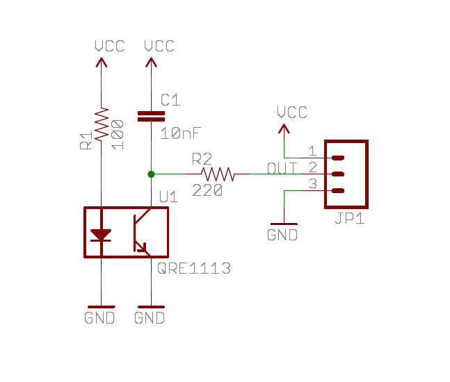
A real-time clock turns off the counter at night to conserve power. When a bee crosses under the LED, the light is reflected back to the sensor, which is a phototransistor, and triggers a digital input to the Arduino...
This frequency counter utilizes an existing digital multimeter (DMM) as the display unit, allowing for a low-cost construction. Due to the high impedance characteristic of most DMMs, a frequency-to-voltage converter can be easily connected without matching issues. The converter...
This article describes a 2-Digit Counter using a Microchip PIC12F629. It shows what can be done with an 8-pin chip having just 5 output lines and one input line. The chip drives two 7-segment displays and this would normally...
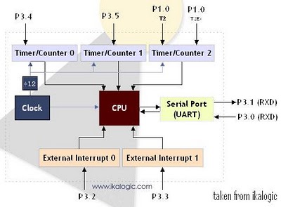
The diagram below illustrates a simplified representation of the main peripherals present in the 89S52 microcontroller, which is part of the 8052/8051 family. The 89S52 includes three Timers/Counters. The term "Timer/Counter" is applicable because this unit can function either...
This project meets a specific need by utilizing a frequency counter built with basic TTL chips, predating the availability of CMOS HC versions. The design incorporates four chips: three HC TTLs and an Atmel AT90S2313 microcontroller. It features a...

An individual sought to utilize a soldering iron to construct a frequency counter, a device that was previously absent in their lab. The schematic for the frequency counter was created using OrCAD PSpice, but the design files have since...