
Theremin Circuit

U2 sections A and B, in conjunction with R13, R14, RV1, and C9, comprise the theremin's local oscillator, adjusted with the PITCH ZERO CONTROL potentiometer and ZERO CAL potentiometer RV1. RV1 is a miniature "trimmer" type, mounted on the circuit board, used to calibrate the local oscillator's frequency range. With RV1 properly adjusted, the local oscillator's frequency will equal the variable oscillator's frequency with the hand furthest away from the antenna. Under these conditions, the phase relationship of the two oscillators will be constant due to their small, but finite capacitive coupling, so no audible tone will be produced. U2 section C buffers the local oscillator's output to provide isolation from the rest of the circuit. The three remaining U2 sections are not used, so their inputs are grounded. Because the theremin's oscillators have some sensitivity to power supply variations, VR1, a low-dropout voltage regulator IC, with C5 and C6, is used to furnish a steady 5 volts. Rectifier CR1 protects the circuit from accidental battery reversal, and R8 prevents excessive current from causing CR1 and the battery to heat under such a condition. The voltage drop across R8 is less than 200 millivolts, causing a relatively insignificant loss in battery life. The theremin typically uses less than 2 milliamperes of current, so a 9 volt alkaline battery will provide many days of operation. The instrument will operate with a battery as low as 5.5 volts.
The inherently low "Q" characteristic of the oscillators establish a limit for the lower audible frequency, below which, electromagnetic interference from power lines and appliances, combined with stray-capacitive coupling between the oscillators, compromise the output fidelity. This effect diminishes if the instrument is far from interfering sources.
The Minimum Theremin may be connected to an amplifier via the OUTPUT JACK. The output voltage level output may vary depending on the specific lot characteristics of ICs used for U1 and U2, but the kits are typically furnished with parts that provide at least 50 millivolts peak-to-peak at 1000 Hertz, adequate for obtaining ample volume. The theremin has sufficient output current to drive efficient, high-fidelity headphones. For use with stereo headphones, the user may wish to replace the jack with a stereo type that has its "tip" and "ring" contacts connected together, or simply use a suitable adapter.
For a theremin to operate properly, sufficient capacitive coupling must exist between the player's body and the instrument. Although not obvious, a player is sufficiently "coupled" to earth via his or her surface area, which presents a large capacitance to earth's ground through "free space." When the theremin is connected to an amplifier, it too, is grounded via an electrical connection and/or capacitance between the amplifier circuitry and earth. This "free space" coupling, along with the amplifier's connection to ground, provide the desired common connection between the player's body and the instrument.
When used with headphones, and not connected to external equipment, there may not be sufficient capacitive coupling between the instrument and player. This may be remedied by connecting the circuit's ground (battery negative terminal) to earth or a nearby metal object. A metal microphone stand, if used to mount the theremin, is suitable for this purpose. If this is not practical, grasping a few coils the headphone cord will provide sufficient coupling between the player and the circuit's ground.
Temperature performance is excellent for this theremin; warm-up drift is negligible due to the conservative power levels in the oscillator ICs, as well as first-order drift cancellation among their similar configurations. The inverters' propagation delays and output impedances are supply-dependent. Accordingly, the PITCH ZERO CONTROL potentiometer affects the local oscillator's frequency by varying its supply voltage. This method of adjustment permits the potentiometer to be located at any convenient distance from the circuit and antenna, since frequency variations resulting from stray capacitance between the potentiometer's slider and ground are decoupled by capacitor C8. In use, the potentiometer is adjusted by the player so that the theremin is silent with the hand furthest away from the antenna, and produces the lowest tone when the hand is at the maximum playing distance.
U1 section F, in conjunction with R3, R4, and R9, is the theremin's mixer. The mixer "heterodynes" the two oscillator signals, producing sum and difference terms of their fundamental frequencies and harmonics. Non-linearities inherent in U1-F's transfer function perform this operation, eliminating the diode normally used for the purpose. C3 is a DC blocking capacitor that couples the mixer's output to a low-pass filter consisting of R7 and C4. This filter attenuates the mixer's inaudible heterodyne sum products, leaving the audible difference, or "beat frequency" product. The beat frequency signal is applied to an amplifier comprised of paralleled U1 sections D and E, and gain-determining resistors R5 and R6. Capacitor C2 provides a second low-pass filtering section to further attenuate the inaudible heterodyne products. DC is blocked from the output by C7, with R10 limiting the output current to prevent damage to U1 and R11 preventing C7 from maintaining a residual charge after power is removed.Two identical integrated circuits, U1 and U2, known as "hex inverters" are used for the theremin's primary functions. They are CMOS (Complimentary Symmetry Metal Oxide Semiconductor) devices, typically used in digital circuits to perform a logic function called "inversion." Each IC contains six identical sections; thus the term "hex inverter." U1 sections A and B, in conjunction with R1, R2 and C1, form the theremin's variable oscillator that operates in a frequency range around 73kHz.
The antenna forms one-half of a variable capacitor that is part of this oscillator's frequency-determining network, and the player's hand forms the other half. As the distance between the hand and the antenna varies, so does the capacitance, and therefore the oscillator's frequency. U1 section C buffers the variable oscillator's output to provide isolation from the rest of the circuit.
U2 sections A and B, in conjunction with R13, R14, RV1, and C9, comprise the theremin's local oscillator, adjusted with the PITCH ZERO CONTROL potentiometer and ZERO CAL potentiometer RV1. RV1 is a miniature "trimmer" type, mounted on the circuit board, used to calibrate the local oscillator's frequency range.
With RV1 properly adjusted, the local oscillator's frequency will equal the variable oscillator's frequency with the hand furthest away from the antenna. Under these conditions, the phase relationship of the two oscillators will be constant due to their small, but finite capacitive coupling, so no audible tone will be produced.
U2 section C buffers the local oscillator's output to provide isolation from the rest of the circuit. The three remaining U2 sections are not used, so their inputs are grounded. Because the theremin's oscillators have some sensitivity to power supply variations, VR1, a low-dropout voltage regulator IC, with C5 and C6, is used to furnish a steady 5 volts.
Rectifier CR1 protects the circuit from accidental battery reversal, and R8 prevents excessive current from causing CR1 and the battery to heat under such a condition. The voltage drop across R8 is less than 200 millivolts, causing a relatively insignificant loss in battery life.
The theremin typically uses less than 2 milliamperes of current, so a 9 volt alkaline battery will provide many days of operation. The instrument will operate with a battery as low as 5.5 volts. The inherently low "Q" characteristic of the oscillators establish a limit for the lower audible frequency, below which, electromagnetic interference from power lines and appliances, combined with stray-capacitive coupling between the oscillators, compromise the output fidelity.
This effect diminishes if the instrument is far from interfering sources. The Minimum Theremin may be connected to an amplifier via the OUTPUT JACK. The output voltage level output may vary depending on the specific lot characteristics of ICs used for U1 and U2, but the kits are typically furnished with parts that provide at least 50 millivolts peak-to-peak at 1000 Hertz, adequate for obtaining ample volume. The theremin has sufficient output current to drive efficient, high-fidelity headphones. For use with stereo headphones, the user may wish to replace the jack with a stereo type that has its "tip" and "ring" contacts connected together, or simply use a suitable adapter.
For a theremin to operate properly, sufficient capacitive coupling must exist between the player's body and the instrument. Although not obvious, a player is sufficiently "coupled" to earth via his or her surface area, which presents a large capacitance to earth's ground through "free space." When the theremin is connected to an amplifier, it too, is grounded via an electrical connection and/or capacitance between the amplifier circuitry and earth.
This "free space" coupling, along with the amplifier's connection to ground, provide the desired common connection between the player's body and the instrument. When used with headphones, and not connected to external equipment, there may not be sufficient capacitive coupling between the instrument and player.
This may be remedied by connecting the circuit's ground (battery negative terminal) to earth or a nearby metal object. A metal microphone stand, if used to mount the theremin, is suitable for this purpose. If this is not practical, grasping a few coils the headphone cord will provide sufficient coupling between the player and the circuit's ground.
Temperature performance is excellent for this theremin; warm-up drift is negligible due to the conservative power levels in the oscillator ICs, as well as first-order drift cancellation among their similar configurations. The inverters' propagation delays and output impedances are supply-dependent. Accordingly, the PITCH ZERO CONTROL potentiometer affects the local oscillator's frequency by varying its supply voltage.
This method of adjustment permits the potentiometer to be located at any convenient distance from the circuit and antenna, since frequency variations resulting from stray capacitance between the potentiometer's slider and ground are decoupled by capacitor C8. In use, the potentiometer is adjusted by the player so that the theremin is silent with the hand furthest away from the antenna, and produces the lowest tone when the hand is at the maximum playing distance.
U1 section F, in conjunction with R3, R4, and R9, is the theremin's mixer. The mixer "heterodynes" the two oscillator signals, producing sum and difference terms of their fundamental frequencies and harmonics. Non-linearities inherent in U1-F's transfer function perform this operation, eliminating the diode normally used for the purpose.
C3 is a DC blocking capacitor that couples the mixer's output to a low-pass filter consisting of R7 and C4. This filter attenuates the mixer's inaudible heterodyne sum products, leaving the audible difference, or "beat frequency" product.
The beat frequency signal is applied to an amplifier comprised of paralleled U1 sections D and E, and gain-determining resistors R5 and R6. Capacitor C2 provides a second low-pass filtering section to further attenuate the inaudible heterodyne products.
DC is blocked from the output by C7, with R10 limiting the output current to prevent damage to U1 and R11 preventing C7 from maintaining a residual charge after power is removed. 🔗 External reference
Related Circuits

The remote control circuit consists of two main components: the transmitter and the receiver. A simple schematic diagram illustrates the remote control setup. The transmitter circuit utilizes a NE555 timer IC to generate a specific frequency. The receiver circuit...
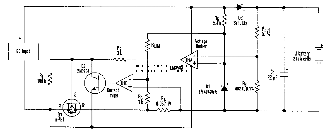
A universal rechargeable lithium battery circuit design, applicable to different battery types and numbers of batteries. This is because both the charger output voltage or current limit setpoint and the maximum charging current can be adjusted by simply changing...
The danger always exists when fuel gases such as propane or natural gas are confined to a small area. The toxic gas alarm utilizes a tin-oxide semiconductor. A coil of thin wire is heated by a 12 V battery...
For the shorter wavelength VHF and UHF bands, it is more practical to construct complex antennas such as a single-band Slim Jim or Yagis. Various projects include creating an electronic unit, as it is necessary for the Intermediate Level...
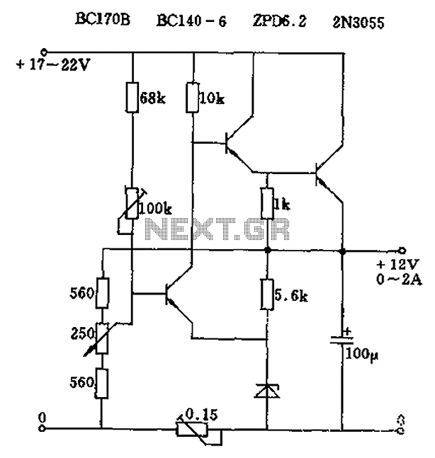
The circuit output voltage can be continuously adjusted from zero to its maximum value. The baseline is established by a constant current sourced from the auxiliary power supply circuit. The reference current of 500 microamperes can be fine-tuned to...
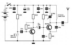
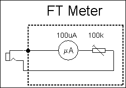
Simple FM Transmitter Circuit This simple FM transmitter circuit was built using a transistor with a transmission distance of about 300m around your home. The simple FM transmitter circuit utilizes a transistor to modulate audio signals onto a radio frequency...