
Parallel DC power supply circuit

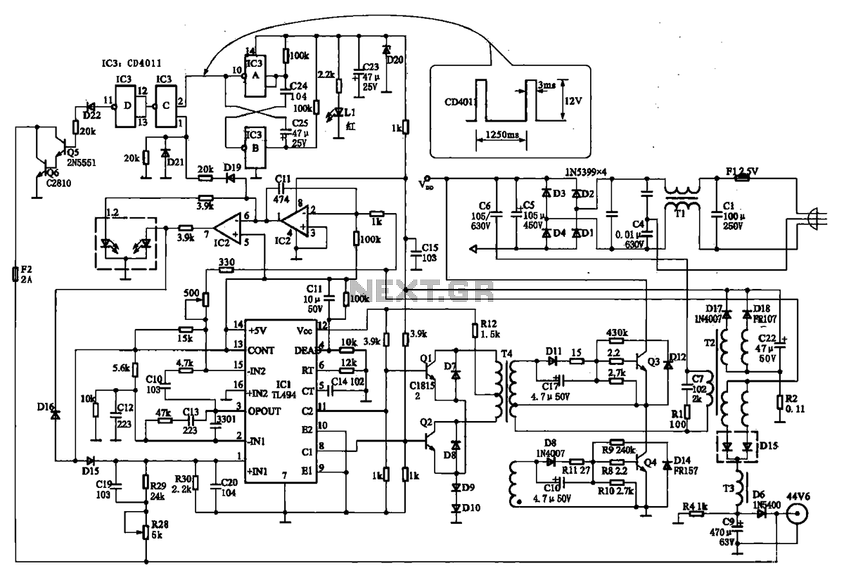
The DC power supply circuit is designed to convert alternating current (AC) to direct current (DC) while ensuring stable voltage output and adequate current limiting for safe operation. The shunt resistor is integrated into the circuit to measure current flow, enabling real-time monitoring and protection against overcurrent conditions.
The rectifier section utilizes diodes arranged in a bridge configuration to efficiently convert the incoming AC voltage to pulsating DC. Following the rectifier, a filter capacitor smooths the output voltage, reducing ripple and providing a more stable DC voltage.
Voltage regulation is achieved through a linear voltage regulator or a switching regulator, ensuring that the output remains at a constant 10V, regardless of variations in input voltage or load conditions. Current limiting is incorporated to prevent damage to the circuit components and the load by restricting the maximum current output.
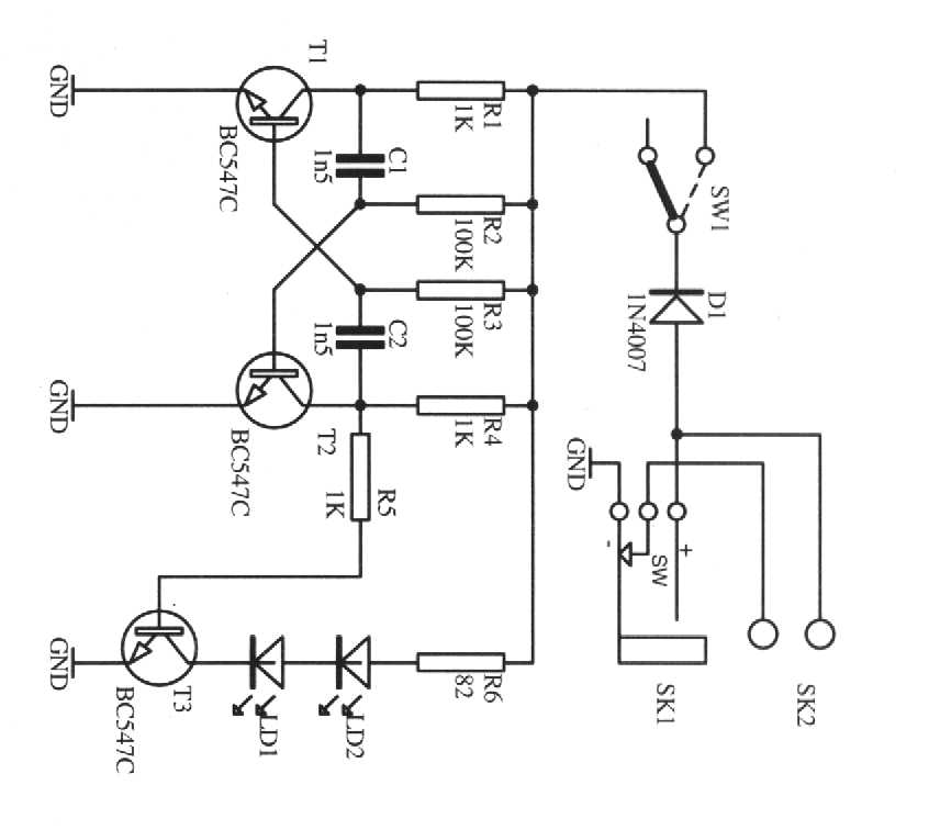
The circuit also includes a 3V indicator system, comprising two indicator lights (EL1 and EL2), which signal the operational status of the machine. These indicators are controlled by a relay circuit that responds to the machine's operational state, illuminating EL1 when the machine is running and EL2 when it is stopped. This feature enhances user awareness and operational safety.
Overall, this DC power supply circuit is characterized by its simplicity, cost-effectiveness, and functionality, making it suitable for a wide range of applications in various electronic devices and systems.DC power supply with shunt, the rectifier, filter, current limiting, voltage regulation, 10V voltage outputs, the circuit is simple, low cost, to meet the requirements of vario us applications, as shown in FIG. FIG. 6. 3V indicator EL1, EL2, respectively, indicating the machine running and stopping, by the relay control circuit.
Related Circuits
The TN-1 Intelligent Negative Pulse Charging Circuit is a sophisticated device designed for efficient battery charging. It operates as a half-bridge charger, which is a common configuration in such circuits. The negative pulse charging mechanism is facilitated by a...
An oscillator is a mechanical or electronic device that operates based on the principles of oscillation. Oscillators serve as fundamental building blocks upon which the entire structure of electronics and computers is established. An article is available that explains...
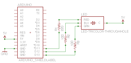
The capability to control lights and fans wirelessly has transitioned from an expensive luxury to widely accessible consumer solutions. Nevertheless, creating a custom solution remains an engaging project for hobbyists and tinkerers. RobotGrrl has developed user-friendly libraries aimed at...
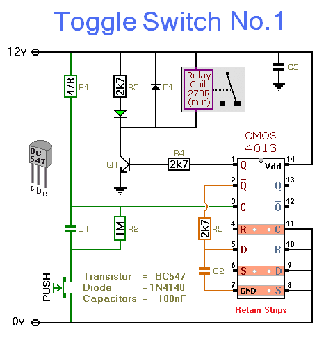
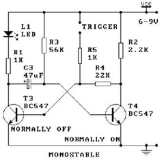
This simple circuit will energize and de-energize a relay with the push of a button. Pressing the button once will energize the relay, while pressing it a second time will de-energize the relay. The accompanying circuit provides a solid...
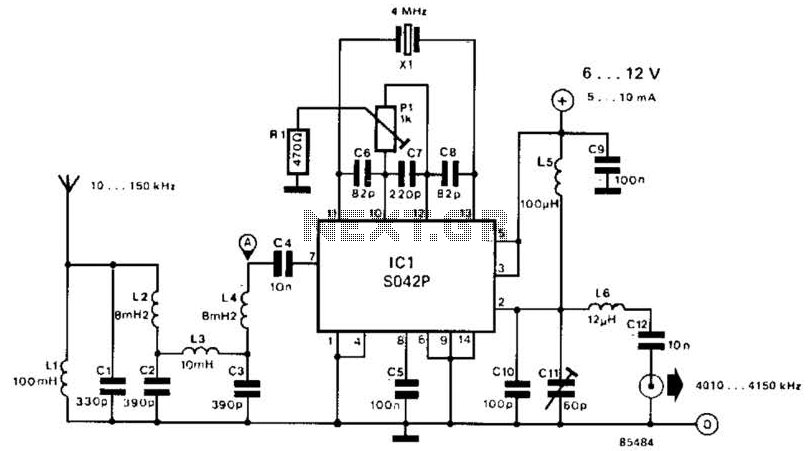
This converter shifts frequencies from 10 kHz to 150 kHz up to 4.01 to 4.15 MHz, suitable for use with a shortwave receiver for very low frequency (VLF) reception. A 4 MHz local oscillator frequency is utilized, and the...
The listed currents represent maximum values, and the actual current consumption will vary based on the circuit's operation. This precludes the simple use of a resistor in series to reduce voltage from 12 volts to 9 volts for powering...