
Mike preamp with tone control

The circuit utilizes the LM318 operational amplifier, which is known for its high-speed performance and wide bandwidth, making it suitable for audio applications. In this configuration, the non-inverting amplifier setup allows for a stable gain with low distortion, which is essential for high-fidelity audio processing. The biasing of the non-inverting input through R1 ensures that the input stage operates correctly by providing a stable reference point for the input signal.
The frequency response of the amplifier is shaped by the components R2 and C2, which create a high-pass filter that effectively rolls off frequencies below 30 Hz. This is particularly useful in audio applications to eliminate unwanted low-frequency noise, ensuring that only the desired audio frequencies are amplified. The gain of the amplifier is set to approximately 50 dB, which is achieved by the feedback network formed by R3. The selection of R3 at 200 kΩ allows for sufficient negative feedback, which stabilizes the gain and improves linearity.
C3 serves as an AC coupling capacitor, preventing any DC offset from affecting the tone control section. This is crucial as tone controls typically operate on AC signals to adjust the tonal quality of the audio output. The tone control section consists of two main parts: the bass control at the top and the treble control at the bottom. Each section is designed using logarithmic potentiometers (R5 and R8), which provide a more natural adjustment of volume levels for human hearing.
The output stage of the preamplifier includes a 50 kΩ potentiometer that allows fine-tuning of the output level. This feature provides the user with the ability to match the output signal level to subsequent audio processing stages or to adjust for different audio sources. Overall, this circuit design is effective for enhancing audio signals while providing user-friendly controls for tonal adjustments.The LM318 op amp is operated as a standard non-inverting amplifier. Resistor Rl (47 k ohm) provides an input path to ground for the bias current of the non-inverting input. The combination of R2 (560 ohm) and C2 (10 /iF) provides a frequency roll-off below 30 Hz. At 30 Hz and above the gain is relatively flat at about 50 dB, set by the ratio R3/R2. R3 (200 k ohm) furnishes negative feedback from the output to the inverting input of thk op amp. C3 (1.0 µ electrolytic) ac couples the preamp to the tone control section. The top half of the tone control section is the bass control. The bottom half controls the treble frequency response. These tone controls (R5 and R8) require audio taper (logarithmic) potentiometers. The 50 k ohm potentiometer on the output can be used to set the output or gain of the preamp.
Related Circuits
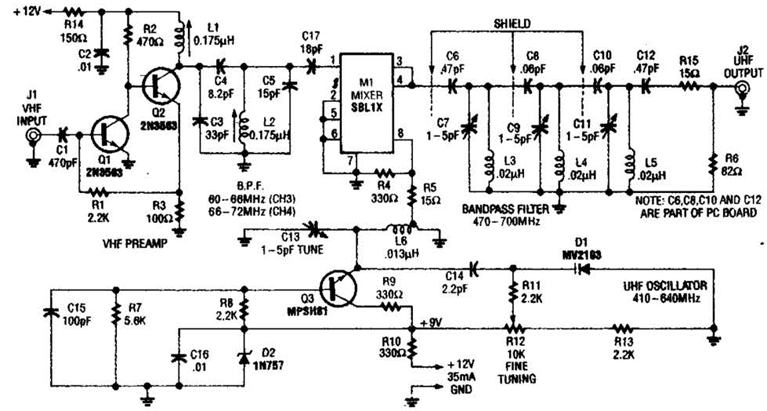
An NE592 or LM733 is utilized as a general-purpose video amplifier in this schematic. J2 and J3 deliver two anti-phase outputs. R2 functions as a gain control. The bandwidth is approximately 100 MHz. The NE592 and LM733 are integrated circuits...
This document serves as a compilation of design notes, providing practical details as construction progresses, along with some photographs that will be included in due course. Currently, it functions as a progress report, blending immediate plans with actual construction,...
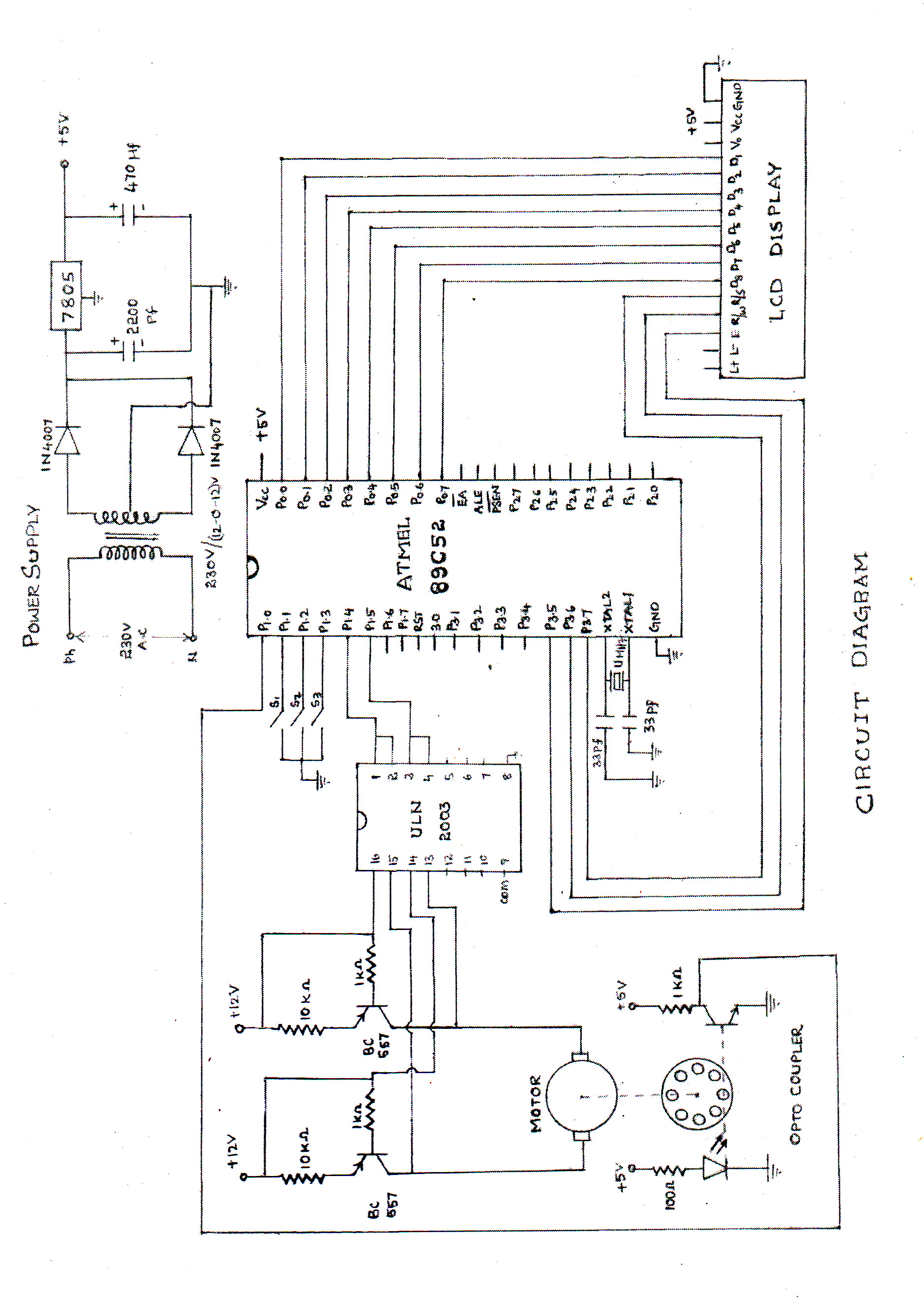
The speed of the DC motor is controlled using an ATMEL89C52 microcontroller, with feedback provided by an optocoupler. The circuit diagram can be viewed above (click on the diagram for a larger view). The motor speed is regulated by...
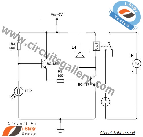
An automatic street light system is increasingly common, providing an intelligent mechanism for street lighting. It automatically illuminates during the night and utilizes incandescent lamps instead of LEDs for energy savings. This document outlines the process of constructing an...
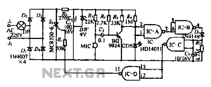
The circuit operates at 380V for air flow. Power is supplied through a step-down transformer, which rectifies the output to 9V DC. When the pump operates correctly, a button labeled 'S' is activated. The circuit utilizes a TWH8778 component....
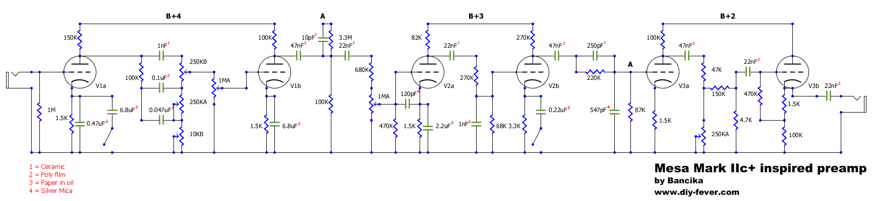
The Mark IIc+ amplifier is highly regarded and sought after, with only 1500 units produced in the 1980s, now valued between $4000 and $5000. One notable artist associated with this amplifier is John Petrucci. Due to affordability issues, a...