
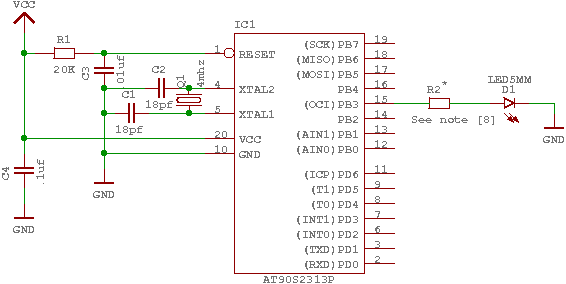
milliohmmeter with AT90S2313
Getting The Drop
The 1 kHz switching signal to the base of the 2N2907 causes 5 volts peak-to-peak to be applied to the 220 ohm resistor in series with the resistance under test, to cause 23 milliamps peak-to-peak to flow through it. One critical part of measuring a very low resistance is developing an IR drop across the resistance, and measuring only that. Getting the IR drop itself was easy, a PNP switching transistor is driven into saturation with the 1 kHz burst, and the transistor's collector delivers 5 volt peak-to-peak pulses to a 220 ohm resistor in series with the resistance under test. The voltage across the 220 ohm resistor is virtually constant as long as the transistor is always driven into saturation and the resistance under test is very low. A 100 milliohm resistance will have a voltage drop of only 2.3 millivolts maximum, so the error introduced by using a 220 ohm resistor instead of a constant current source is only 2.3 mv/5v = 0.05%, so this approach is sufficient for a 100 count meter.
While testing the circuit it was noted that when leaving the input open circuited, the meter gave a very low resistance measurement. An investigation revealed that when the meter's input terminals were unloaded, there was virtually no signal across the input terminals. Without the test resistance in series with the 220 ohm resistor, there was no signal; the input simply charged up to +5 volts and exhibited minor fluctuations due to capacitive coupling between the transistor's base and collector. To mitigate this issue, a 10k resistor was added from the PNP's collector to ground, enhancing circuit stability.
To ensure accurate measurement of the resistance under test and to eliminate the influence of test lead resistance, a four-wire measurement system was implemented. This system utilizes two wires to deliver the test current and two separate wires to measure the voltage drop. Careful attention was given to the circuit layout to maintain separation between the test current ground return path and the voltage sense ground line. The terminal marked "Test Current Return" connects directly to the battery's negative terminal, while the "Small Signal Return" connects to the analog circuit grounds, merging with the battery ground at the location where the 1.8 volt reference voltage is generated. This configuration ensures that the measurement is accurate and unaffected by extraneous resistances in the test leads.A milliohmmeter is just the tool for checking trace resistance on a printed circuit board, tracking down shorted traces, and measuring the contact resistance of a switch or connector. Its the kind of tool that would come in real handy occasionally, but not often enough to justify shelling out hundreds of dollars.
Wanting one anyway, I set out to make my own. It turned out to be not only an exciting project, but a true adventure of discovery as it provided a window into the workings of lock-in amplifiers. In this circuit, shown in the block diagram in figure 1, a 1 kHz burst of 5 volt peak pulses is applied to a series dropping resistor to establish a pulsing current through the resistance under test.
The IR drop across the resistor under test is a voltage proportional to the value of the resistance. After passing through a high pass filter to eliminate the DC component of the signal, it is rectified by a synchronous demodulator.
For a period of time corresponding to the burst, the rectified signal is applied to an integrator, which charges up, and then at the end of the burst, the time it takes the integrator to discharge at a constant rate is measured to determine the size of the charge, and that is how the average amplitude of the signal applied to the integrator is determined. Since random noise is not synchronized with the switching in the synchronous demodulator, it is not rectified and it averages out to nearly zero.
The longer the integration time, the less proportionate effect a given small pulse of noise has on the integrator's output, and the more gain the integrator has for the 1 kHz burst. Integration is the wonder of lock-in .amplification Getting The Drop \ figure 2 The 1 Khz switching signal to the base of the 2N2907 causes 5 volts peak-to-peak to be applied to the 220 ohm resistor in series with the resistance under test, to cause 23 milliamps peak-to-peak to flow through it.
One critical part of measuring a very low resistance is developing an IR drop across the resistance, and measuring only that. Getting the IR drop itself was easy, a PNP switching transistor is driven into saturation with the 1 kHz burst, and the transistor's collector delivers 5 volt peak-to-peak pulses to a 220 ohm resistor in series with the resistance under test (see figure 2).
The voltage across the 220 ohm resistor is virtually constant as long as the transistor is always driven into saturation and the resistance under test is very low. A 100 milliohm resistance will have a voltage drop of only 2.3 millivolts maximum, so the error introduced by using a 220 ohm resistor instead of a constant current source is only 2.3 mv/5v = 0.05%, so I think you will agree that this approach is sufficient for a 100 count meter.
While testing the circuit I was surprised that when leaving the input open circuited, the meter gave a very low resistance measurement. I spent a long time looking over the firmware, looking for math errors or register use conflicts, before I decided to take a look at the circuit with an oscilloscope.
That's when I saw that when the meter's input terminals were unloaded, there was virtually no signal across the input terminals. Without the test resistance in series with the 220 Ohm resistor, there was no signal - the input just charged up to +5 volts and wiggled a little because of capacitive coupling between the transistor's base and collector.
That's when I added the 10k resistor from the PNP's collector to ground. I should have taken my early mentor's advice, "Always look for the simplest explanation first." To make sure that I am only measuring the resistance of the thing I am trying to measure and not the resistance of my test leads, I used a 4 wire measurement system. In this system, two wires are used to deliver the test current and two separate wires are used to measure the voltage drop.
Simple enough, but how did I keep the test current ground return path separate from the voltage sense ground line? There in lies much of the art in circuit layout. Looking at figure 2, the terminal marked "Test Current Return" connects directly to the battery's negative connection to the circuit.
The signal marked "Small Signal Return" connects to the rest of the analog circuits' grounds, and then joins up with the battery ground at the point in the circuit where the 1.8 volt reference voltage is generated. 🔗 External reference
Related Circuits
The GNU tools must be configured, built, and installed on the system. This chapter presents a simple example of using the GNU tools in an AVR project. After reviewing this chapter, users should gain a better understanding of how...

The ATMEL AVR family has established a strong presence in the microcontroller market. These microcontrollers offer a fast core and a variety of peripherals, which continue to attract the attention of engineers and gain their preference. Developers will find...
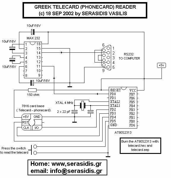
This circuit functions solely as a reader and is not designed for programming. It cannot be used to refill, hack, or perform any illegal activities with telecards. The primary purpose of this circuit is to demonstrate how a microcontroller...
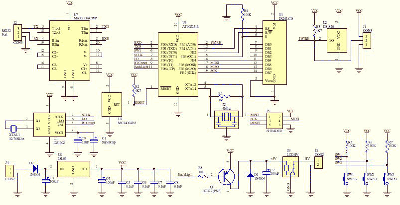
This is the fully featured, jammed packed temperature readout unit. I can measure temperature from up at 8 DS1820 digital temperature sensors all on the same 1-wire bus. That's right only 3 wires are needed to go to all...
This project meets a specific need by utilizing a frequency counter built with basic TTL chips, predating the availability of CMOS HC versions. The design incorporates four chips: three HC TTLs and an Atmel AT90S2313 microcontroller. It features a...
Its an adaptation of the 2X 16 LCD project, by adding a ferrite loop antenna, two resistors, and a capacitor. Here the display shows the output of the 10 bit scanning voltmeter with Minimum Mass Wireless Coupler. Both the...