
Remote control by mobile phone

The received signals are amplified by T1 and then applied to pin RB2 of the central microcontroller, a PIC16F84 (IC2). DTMF stands for dual-tone multi-frequency, a tone coding/decoding system that`s been in use on wired telephone sets for almost 30 years now.
Each key on the DTMF keypad is linked to a combination of two (nonharmonically related) tones in the audible range. At the receiving side, the tone pairs are decoded into the matching number (0-9, #, *). For our application, the mobile phone is set to auto-answer mode. In operation, the PIC micro will continuously monitor the level at RB7 (pin 13). A ring signal will wake up the PIC from its sleep state and cause it to activate the speech chip (IC3) which supplies a spoken` message to the mobile phone via the microphone connector of the headset.
At the calling end, the user hears the welcome message and is prompted to enter the system password (MSG1). The level of the audio signal may be adjusted on preset P2. The selection of spoken text stored in the speech chip is determined by the logic state of control lines A6, A7 and A8.
Next, the program running inside the PIC will wait for certain DTMF tones entered by the user on his/her phone (mobile or landline). The received DTMF signals are decoded into the matching numbers by IC1, which supply binary output information on outputs Q1-Q4, with output STD (pin 15) flagging reception of a valid code to the PIC.
Having received a valid 4-digit password (which is being compared to the one stored in the PIC`s memory), the system will request a function code (MSG2). Depending on the information received in response to MSG2, the micro will pull its RB5 control line logic Low or High.
This signal enables a relay to switch a suitably wired up electrical appliance in your home to be switched on or off (for example, a coffee machine or the central heating). The relay may be a solid-state device (which allows direct control from RB5), or a traditional solenoid-based switcher that`s controlled via a transistor buffer.
The action executed at the receiving side is confirmed with a spoken message (MSG4 or MSG5). The speech chip contains yet other text messages (MSG3, MSG6 and MSG7) for the processing of situations out of the ordinary`. The spoken messages are supplied by a type ISD25120 speech synthesiser which has storage capacity for about two minutes worth of speech.
Different memory areas inside the ISD25120 may be selected using address lines A0-A9. Here, the memory has been divided into eight chunks of about 15 seconds that can be individually addressed over A6, A7 and A8. This allows the PIC to select any individual spoken messages and have it played back by pulling the CE control input Low.
The spoken messages may be recorded and checked using a microphone and a small loudspeaker connected to IC3. Switches S4, S5 and S6 select the relevant memory area. The relevant message is then recorded on the chip via MIC1 while S2 is pressed. The pushbutton should be released at the end of your message, which can be listened to by briefly pressing S1 (this requires switch S7 to be closed).
If you are not satisfied with the result, the text may be re-recorded. During recording ad playing back the messages (for checking) the PIC has to be removed from its socket, else IC3`s address lines cannot be set manually. The inset Messages` gives examples of texts you could use for the voice feedback, including the associated address settings.
In an application like this, where equipment is controlled from a remote location, it is essential to prevent unauthorised access. In any case, password protection is required. You, the user, may pick your own 4-digit password using the number keys on your mobile phone`s keypad.
For this to work you have to open switch S3 (which is closed during normal use). In that case, the four numbers entered on the calling phone after the welcome message has finished will be accepted as the new password, and subsequently stored in the PIC`s RAM memory. If mains outages are common in your home, we recommend powering the circuit from a battery system with mains charging, else the password will be lost.
Figure 2. Copper track layout and component mounting plan of the PCB designed for the remote control. Be sure to use sockets for the ICs, as the PIC has to be removed during recording of the spoken messages. The above article text having largely described the operation and practical use of the circuit, you should know the function of all switches and other controls and use this information to fit the relevant parts on the case in such a way that the unit is easy to operate in practice.
The source code of the PIC control program written by the author is available as a free download from our website, as well as on floppy disk (order code 040415-11). Those without access to a suitable PIC programmer may also buy the PIC micro ready-programmed as The PCB artwork is shown at true size in Figure 2.
With all components fitted (insert the ICs in sockets) the controls may be connected up via short lengths of stiff wire: S1, S2, S3, S4, S5 and S6, the electret microphone capsule and (if required) the loudspeaker (together with S7). The latter parts are mainly needed to check the spoken messages, switch S7 allowing the loudspeaker to be switched off during normal use.
Next, the mobile phone link may be hooked up on connector K1. The output relay for the electrical appliance you wish to control (literally from anywhere in the civilised world!) is connected to the terminals beside S3 on the board. The circuit is happy with a 6-15 VDC supply voltage from a mains adaptor capable of supplying 100 mA or so.
There is only one adjustment in the circuit: preset P1 determines the input sensitivity of the DTMF IC. The setting is not critical however and the circuit will usually work with the wiper at mid travel. 3. The mobile has to support auto-answer mode`, that is, it has to be able to answer an incoming call on the first ring signal.
Some mobiles will not show this option until a headset is actually connected. 4. The ring signal has to be audible in the headset, too, as it its something into the calling phone. 🔗 External reference
Related Circuits
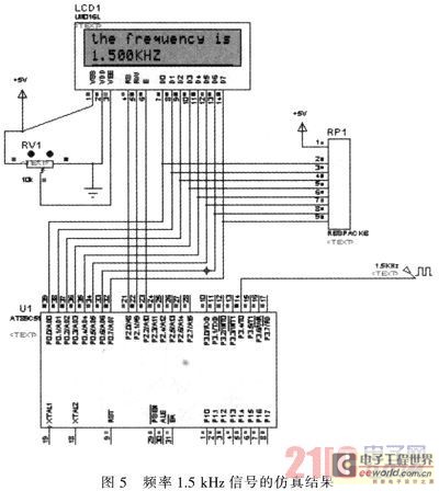
The primary function of the frequency counter is to measure the frequency and cycle of a signal. Its applications span a wide range, extending beyond simple instrument measurements to areas such as education, scientific research, high-precision instrument measurement, and...
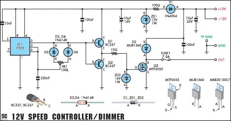
This circuit serves as a speed controller for a 12V motor with a continuous rating of up to 5A or as a dimmer for a 12V halogen or standard incandescent lamp rated up to 50W. It regulates power to...

Utilize a PIC Microcontroller to Control a Hobby Servo. This guide outlines the process of incorporating hobby servos, typically found in remote-controlled airplanes, cars, and similar devices. To implement the control of a hobby servo using a PIC microcontroller, the...
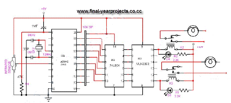
This is a comprehensive electrical project report on an Infrared Remote Control On/Off Switch, submitted to fulfill the requirements for the Bachelor of Engineering degree in Electrical Engineering. The project is designed to control the operation of home appliances...
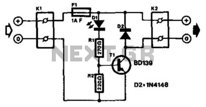
The LED with an integrated flasher is connected in series with the base-emitter junction of transistor T1. Consequently, the load connected to K2 is switched on and off in sync with the flash rate. This load can be a...
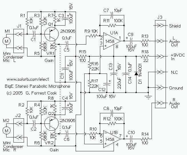
This device is a stereo amplifier for a high sensitivity stereo parabolic microphone. It can be used for listening to distant sounds. The Big-E can be used with headphones or as an audio source for a stereo tape recorder...