
Mini-box 2W Amplifier

The described amplifier circuit is a compact, discrete-component design aimed at providing high-fidelity audio amplification while maintaining simplicity and ease of assembly. The architecture typically involves a class AB amplifier configuration, which is well-regarded for its efficiency and sound quality.
The input stage of the amplifier accepts line-level signals from various audio sources, such as portable music players and computers. This input can be connected through a 3.5mm jack or RCA connectors, allowing for versatile compatibility with consumer audio devices. A coupling capacitor may be employed to block any DC offset from the input source, ensuring that only the audio signal is amplified.
The amplifier employs a pair of complementary output transistors, usually a combination of NPN and PNP types, arranged to drive the speaker load effectively. This arrangement minimizes crossover distortion, a common issue in audio amplification, by ensuring that one transistor conducts during the positive half-cycle of the audio signal while the other takes over during the negative half-cycle.
To further enhance performance, the circuit may include feedback mechanisms that stabilize gain and improve linearity. A resistor-capacitor (RC) network can be implemented to set the frequency response of the amplifier, allowing it to handle a wide range of audio frequencies while attenuating any unwanted high-frequency noise.
Power supply considerations are crucial for the operation of the amplifier. The use of a 12V wall plug-in transformer simplifies the power supply requirements, providing a stable voltage while ensuring safety and ease of use. Decoupling capacitors are typically placed near the power supply pins of the amplifier to filter out noise and provide a clean power source for optimal performance.
For stereo applications, two identical amplifier circuits would be constructed, each housed in its own enclosure, allowing for the separation of left and right audio channels. This configuration not only enhances the listening experience but also provides the flexibility to adjust each channel independently if needed.
Overall, this amplifier design emphasizes traditional engineering principles, focusing on reliable performance, ease of construction, and accessibility of components, making it suitable for both hobbyists and audio enthusiasts seeking a straightforward amplification solution.This amplifier was designed to be self-contained in a small loudspeaker box. It can be feed by Walkman, Mini-Disc, iPod and CD players, computers and similar devices fitted with line or headphone output. Of course, in most cases you will have to make two boxes to obtain stereo. The circuit was deliberately designed using no ICs and in a rather old-fashioned manner in order to obtain good harmonic distortion behavior and to avoid hard to find components. The amplifier(s) can be conveniently supplied by a 12V wall plug-in transfor 🔗 External reference
Related Circuits
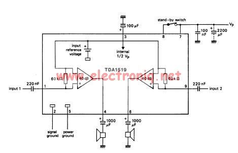
The TDA1519 circuit can deliver 2x6 watts output power. TDA1519 is an integrated class-B dual output amplifier in a 9-lead single in-line (SIL) plastic medium power package primarily developed for car radio applications. The TDA1519 is a robust integrated circuit...
The TDA8581 from Philips Semiconductors is a 1-watt Bridge Tied Load (BTL) audio power amplifier capable of delivering 1 watt output power into an 8 ohm load. The TDA8581 is designed for audio amplification applications, particularly in consumer electronics such...
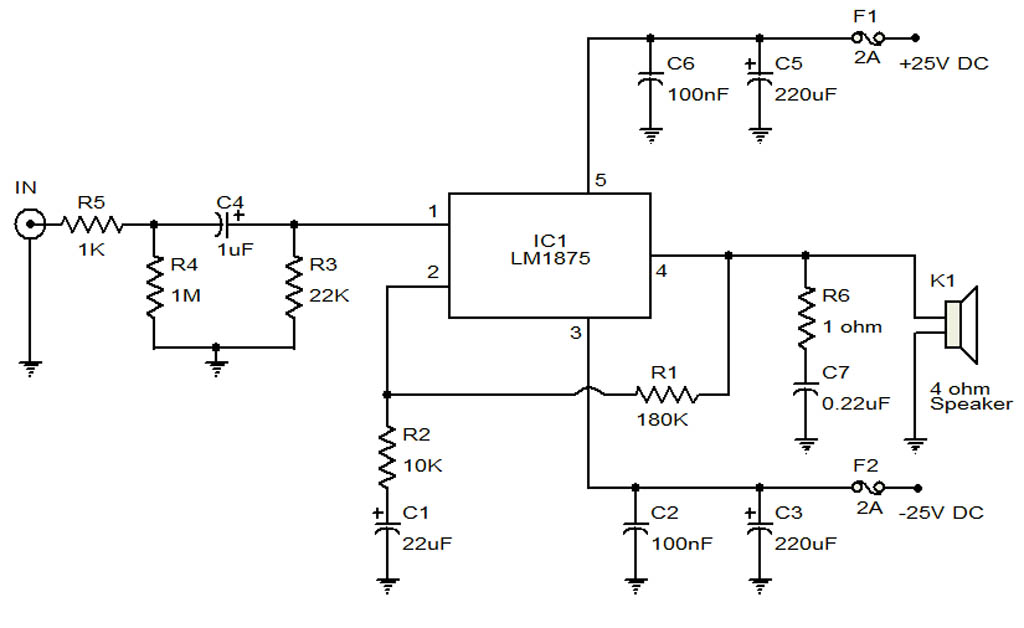
The circuit illustrates a 20-Watt audio amplifier diagram based on the LM1875 integrated circuit (IC). It is designed for use in automotive applications and provides an output power of 20 Watts. The 20-Watt audio amplifier circuit utilizing the LM1875 IC...

This circuit features a high-input-impedance AC resistance of 880 kΩ and a gain of 10, utilizing an operational amplifier for a piezoelectric transducer. The described circuit is designed to interface with a piezoelectric transducer, which generates an AC voltage in...
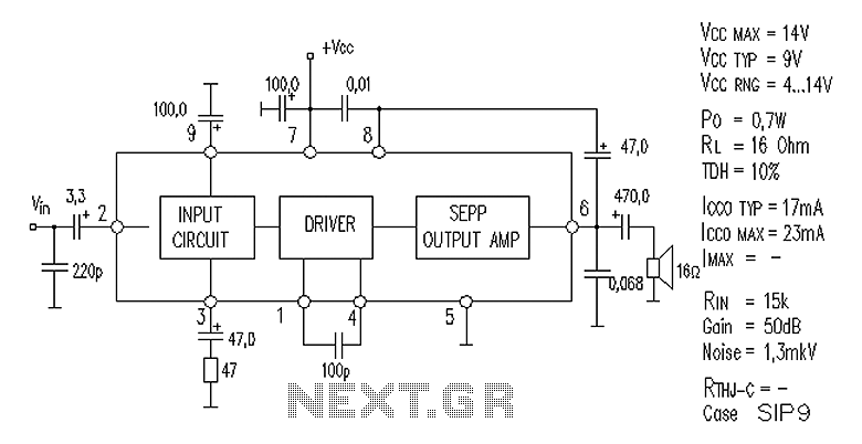
AN7112 power amplifier circuit diagram The AN7112 is a power amplifier designed for audio applications, capable of delivering high output power while maintaining high fidelity. The circuit diagram typically includes essential components such as transistors, resistors, capacitors, and a...
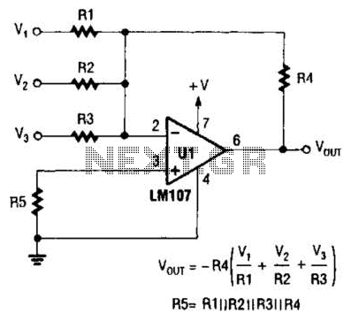
The output of Ul is the sum of Vv, multiplied by the ratio of Rx to Rv, RJRV, and respectively. Resistors R1, R2, and R3 are selected as required for individual gains. Additionally, R4 influences the gain of all...