
mini logger circuit

The MiniLOGGER circuit design includes key components that facilitate data acquisition and processing. The 8-channel analog input allows for diverse signal monitoring, while the pulse input expands the functionality for digital signal capture. The 256kB SRAM ensures ample storage for recorded data, supporting long-term logging without the need for constant power. The Real-time Clock (RTC) is crucial for timestamping each data entry, enabling accurate time-based analysis.
The communication interface via RS232C allows for straightforward integration with computers and terminal emulation software, ensuring ease of data retrieval. The manual switch feature provides flexibility in operation, allowing users to initiate recording without needing a computer connection, which is beneficial for field applications.
The analog signal conditioning can be tailored to specific sensors, such as the Pyranometer and LM35, enhancing measurement accuracy. The use of a non-inverting amplifier configuration ensures that the signals from these sensors are amplified appropriately for the ADC input of the MiniLOGGER. The design considerations for filtering and gain adjustment are critical for achieving the desired sensitivity and precision in measurements.
Future enhancements could include the integration of additional communication protocols, such as USB or wireless connectivity, to streamline data transfer and improve user accessibility. Additionally, expanding the firmware capabilities to include more advanced data processing features could enhance the overall functionality of the MiniLOGGER, making it a versatile tool for various experimental applications.Build your own a personal data logger for recording analog signal. The MiniLOGGER provides 8-channel analog input(-99mV to +999mV), 1-channel pulse input, battery backup 256kB SRAM, Real-time Clock, and RS232C. Start/Stop recording can be made by MANUAL switch or preprogrammed Start/Stop Time. The format of uploading data is ASCII format, suitable for importing and graphing by Excel or any Scientific Plot Program. Exemplary circuit used for measuring Insolation and Air Temperature vs. Time is included. I have designed the MiniLOGGER to be used as a data acquisition module for my experiment, "Long-term Evaluation of Grid Connected PV System". Formerly, there`s a signal conditioner board having chopper stabilized DC amplifier for Pyranometer, HALL sensor, LM35, and kWhr sensor, it`s called Solar-Logger.
The firmware of Solar-Logger was written entirely in assembly code, very difficult for maintenance and modification. So I decided to rewrite using `C` and to provide this page describing how to build the generic part, without analog signal conditioner, with new name, the MiniLOGGER.
Those who interested, for her/his experiment can be made themselves, the analog conditioning board to suit their experiment easily. I shall provide the circuit of analog signal amplifier to be used with the MiniLOGGER on later. Run terminal emulation program, say HyperTerminal configured with 9600 bps 8n1, Xon/Xoff flow control, connect RS232C serial port of the MiniLOGGER to COM1.
After put a DC adapter, press enter, MiniLOGGER will send title message. Try with ` ` help command. The MiniLOGGER accepts single letter command as describe in help command. Manual START/STOP recording is the easiest way of using in standalone mode, i. e. , without connecting to web server. Manual switch connected to P3. 2 provides a logic `0` making the MiniLOGGER started to record and when open, P3. 2 be a logic `1`, stop recording. In this mode, user must set START/STOP TIME to 99:99 to disable automatic mode. The interval between sample that saved in NVSRAM is restored the last set when power up the LOGGER again. In Automatic mode, the LOGGER will start record when time of clock read from DS1202 is equal to preset START time and stop record when equal to preset STOP time.
During in recording, after finish saving each record, the number of record will send through TxD pin. In both mode, while in standby or stop recording, the LED will blink at 1Hz rate, but while recording, the blink rate will be 3Hz.
When using manual mode, after setting interval with `i` command, and set START/STOP TIME to 99:99 by using a PC, we may turn the power supply off. Take the MiniLOGGER to the place for experiment, turn the power on, the LED will blink at 1Hz rate. To start recording, just close MANUAL switch, the LED will blink every 3 sec. When finished logging the data, turn MANUAL switch open, turn the power off, take to the lab connecting to a terminal for uploading with `r` and `a` command.
Uploading and capturing the recorded data is easily be made by using Capture Text. After put a name of capture text file, enter >>a, All read command, all records will then be saved into capturefile. txt Figure 5 depicts a simple DC amplifier for Pyranometer and LM35 temperature sensor IC. The amplifier is configured to be non-inverting DC amplifier using chopperless precision opamp, OP07.
The sensitivity of Pyranometer is 14uV/ W/m2, to amplify for 1mV/W/m2, the gain should be approx. 71. Since the gain of noninverting type is approx. (1+Rf/1k), where Rf is 10 turn 100k variable resistor. A 1k and 10uF forms a low-pass filter. Air temperature is easily be measured by using LM35 IC. However, biasing of the LM35 is done with single-end supply, thus the circuit shown in Figure 5 can be used for measuring temperature from 0 - 50C, say. The ASCII text file of the record can be easily imported into Excel worksheet. Figure 8 shows example grap 🔗 External reference
Related Circuits
These circuits could be used as the basis for Model Railroad DCC Boosters or PWM motor controllers. The first schematic is for a basic 3 Amp - DCC Booster using the LMD 18200 CMOS, H-Bridge. Included in the design...
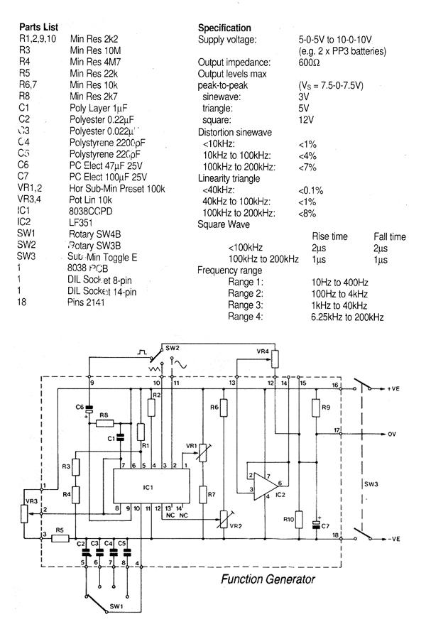
This generally results in a square wave if the frequency of oscillation is low enough relative to the amplifier's bandwidth. The schematic of a crystal-controlled oscillator features a low-frequency sine wave oscillator characterized by low distortion, wideband operation, and...
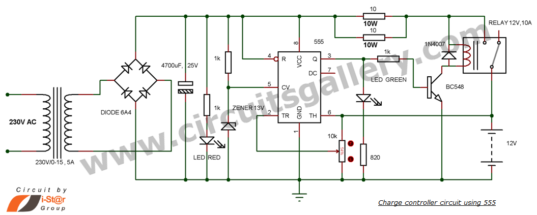
This is a simple DIY charge controller schematic created in response to a request from one of the readers on our Facebook page. The primary component of this automatic battery charger circuit is a 555 timer, which compares the...
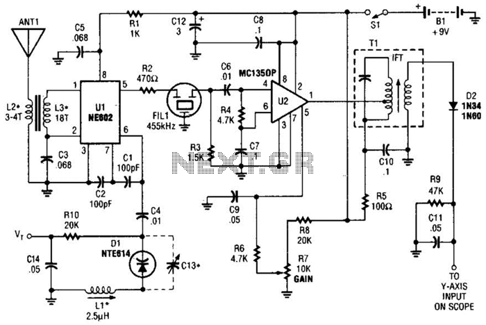
This circuit is designed for monitoring an amateur band or a specific segment of the radio spectrum. It utilizes an NE602 mixer-oscillator chip to generate a 455-kHz intermediate frequency (IF) signal. This signal is amplified by U2 and subsequently...
The following circuit illustrates the use of the AD8531 integrated circuit for the automatic control of LCD panel backlighting. Features include the ability to compensate for aging effects. The AD8531 is a precision operational amplifier that is well-suited for applications...
The simple bell circuit without IC. It includes a doorbell circuit that can produce different sounds using integrated circuits, transistors, and resistors. The circuit utilizes a coded trigger mechanism to differentiate between various visitors. When the button is pressed,...