
miniature audio amplifier

The amplifier includes miniature speaker cabinets, with speakers approximately 57 mm in diameter sourced from a PC case. Although eight speakers were chosen, only two were found to be applicable. Half of them were unsuitable due to scrubbing, while the rest exhibited different sensitivities and tonal qualities. The final boxes utilized small speakers with a plastic membrane purchased from GES in the store. Ideally, medium to large elliptical speakers with AlNiCo magnets should be used, as they possess a low stray field. These speakers can sometimes be found for sale or salvaged from old television sets. The miniature speakers were subsequently replaced with larger elliptical speakers (used in TVs) that provided significantly better sound quality. The original low-frequency correction was no longer sufficient. Modifications to the wiring are indicated in red in Figure 4, and Figure 5 presents the frequency characteristics in the low frequencies before and after treatment.
Component Specifications:
- R1, R2, R5, R6: 22 Ohm (SMD 1206)
- R3, R4: 2.2 kOhm (SMD 1206)
- R7, R8: 4.7 Ohm (SMD 1206)
- P1: 4.7 kOhm, logarithmic potentiometer stereo Radiohm
- C1, C2, C7, C8, C9: 100 nF (SMD 1206)
- C3, C4: 100 µF/10V
- C5, C6: 470 µF/10V
- C10: 1947 µF/16V
- IO: TDA2822M
- Connector: 3.5mm stereo jack socket SCJ-0354-5PU
- Connectors: 2x RCA
- Connector: 3.5mm stereo plug
- Connector: CANNON 15M
- Pack: KM27
- Shielded cable: PCB bcs37
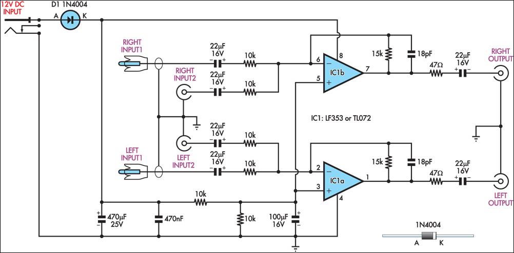
The amplifier performs optimally with an external power source, as opposed to "flat" batteries. It is crucial that the power supply is never shorted. The load collection should be up to 5 mA, opening to 200 mA (5 V supply). The amplifier is designed to function correctly on the first connection. It can also be utilized in conjunction with a Walkman or CD player, necessitating an external power source such as a battery or AC adapter.The amplifier is based on an integrated circuit TDA2822M. With this circuit can be built amplifier with up to 2 1 W. This much power circuit is able to supply only at peak times, the continuous excitation would not be able uchladit. Involvement of the amplifier is to figure 1 . The input signal passes through a frequency divider depends on the volume control. Frequency-dependent divider zd?raz?ujuje frequencies around 100 Hz, which has a positive effect on the subjective sound quality when using small speakers.
IO is involved in the manufacturer's recommendations. The amplifier output can connect speakers with impedance of 8 ohms (or greater), or headphones. Power supply IC can be in the range 1.8 to 15 V. The low supply voltage power amplifier is very small, at high supply voltage and load speakers with low impedance circuit may be a little overheated. With 8 ohm speakers should be power supply voltage of 6-9 V. I used a 5 V supply voltage, which is derived from the game port. Voltage of 5 V can be obtained even from the keyboard connector, PS / 2 port and USB. A better option is a network adapter, there are no problems with earth loops. The amplifier is built on a printed circuit board according to Figure 2 and 3 . SMD resistors and capacitors are mounted on the circuit, other components are soldered in the normal way.
The board is in a box attached at KM27 headphone jack and a potentiometer bracket to the side of the box. In the absence of other suitable connectors for connecting the speakers I use RCA connectors. To connect the input signal can be used jack 3.5 mm (the box is not fit) or a molded connector. For this amp I used a 4-wire shielded cable. Two cores are used for audio signal, the remaining supply voltage. Power supply is taken from the game port on Pin 1 Ground wire (0V) is connected to the outlet of the fourth Current links countries konktoru game port and audio output from the PC establishes a connection to ground loop, implemented in the sample, but not disruptive intentions.
The amplifier I made a miniature speaker cabinets, speakers that I planted about 57 mm diameter of the PC case. Although I chose the eight pieces, I found two applicable. About half of them scrubbing, all the rest have different sensitivities and different tone colors. I finally finished boxes already used tiny speakers with a plastic membrane purchased GES in the store.
The best would be to use a medium to large elliptical speakers with AlNiCo magnet (small round), which have a low stray field. These reprodukrory can sometimes get in sales or you can dismantle the old television sets. Miniature speakers I swapped for a bigger litter box with elliptical speakers (used in TV) with much better sound.
The original "correction" the low frequencies, then no longer meet. Figure 4 is a modified wiring changes are marked in red. Figure 5 is a characteristic frequency in the low frequencies before and after treatment. R1, R2, R5, R6 22 Ohm (SMD 1206) R3, R4 2.2 kOhm (SMD 1206) R7, R8 4.7 Ohm (SMD 1206) P1 4.7 kOhm, logarithmic potentiometer stereo Radiohm C1, C2, C7, C8, C9 100 nF (SMD 1206) C3, C4 100 ?F/10 In C5, C6 470 ?F/10 In C10 In 1947 ?F/16 IO TDA2822M connector 3.5mm stereo jack socket SCJ-0354-5PU Connectors 2x RCA connector 3.5mm stereo plug connector CANNON 15M pack KM27 shielded cable PCB bcs37 Amplifier will boost best with external power, just as "flat" batteries. It is important that the power supply should never short. Collection of load should be up to 5 mA, opens, then to 200 mA (5 V supply). Involvement has no guile, and should work on the first connection. The amplifier can also be used in conjunction with the Walkman or CD player. In this case, you need an external power source - battery or AC adapter. 🔗 External reference
Related Circuits
The simplest way to bias a transistor amplifier is through a fixed-bias circuit. The supply voltage is connected to the base terminal of the transistor via the R1 current-limiting resistor. The bias resistor value is typically chosen based on...
This circuit is primarily designed to provide a microphone input for standard home stereo amplifiers. Utilizing a battery supply effectively eliminates the risk of low-frequency hum interference from mains power, simplifying the connection to the amplifier by removing the...
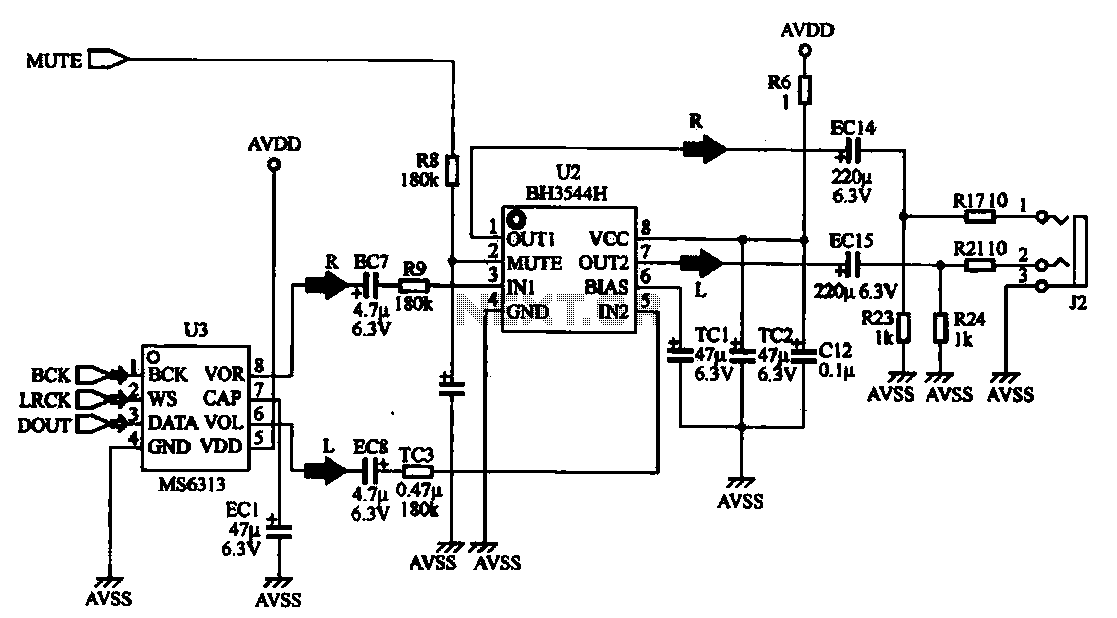
The MP4 audio circuitry consists of audio D/A converters and an audio amplifier combination circuit. This design features a straightforward circuit layout, making it suitable for integration into compact MP4 digital devices. The MP4 audio circuitry is designed to efficiently...

The circuit is a high-power car audio amplifier schematic. It functions as a car audio amplifier using the PA02 and LH0101 integrated circuits (ICs). Each IC delivers an output power of 30W with an 8-ohm impedance. The part list...
This circuit combines two separate line-level stereo (left and right) signals into a single stereo output, eliminating the need to switch between two sets of input signals. In this application, it is utilized to connect stereo audio from a...
As with any audio mixer circuit, a slight loss is always introduced. The final summing amplifier has a gain of 2 or 6dB to overcome this. The input line level should be around 200mV RMS. The mic inputs are...