Sequential ac flasher
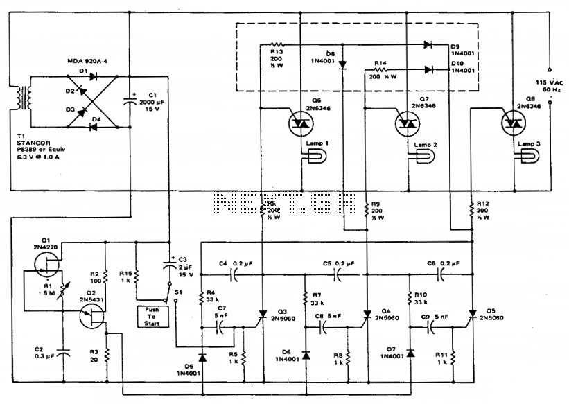
This circuit employs a ring counter consisting of Q3, Q4, and Q5. Q2 functions as an oscillator that sequentially triggers the SCRs Q3, Q4, and Q5. When an SCR is activated, a 0.2 µF capacitor facilitates commutation, turning off the preceding stage. Triacs Q6, Q7, and Q8 are responsible for controlling lamps 1, 2, and 3, respectively.
The described circuit utilizes a ring counter configuration to manage the operation of several components in a sequential manner. The ring counter is constructed using three silicon-controlled rectifiers (SCRs), designated as Q3, Q4, and Q5. The oscillator, represented by Q2, generates a periodic signal that drives the SCRs in a specific sequence. This sequential triggering is crucial for the effective operation of the circuit, as it ensures that only one SCR is active at any given time.
When Q2 oscillates, it sends a triggering pulse to the first SCR in the sequence. Upon activation, this SCR allows current to flow through it, powering the connected load. In this case, the load is represented by the lamps controlled by the triacs (Q6, Q7, and Q8). Each triac corresponds to a specific lamp, allowing for independent control of lamps 1, 2, and 3.
The inclusion of a 0.2 µF capacitor serves a vital role in the circuit's operation. When an SCR is triggered, the capacitor provides the necessary energy for commutation, effectively turning off the previous SCR in the sequence. This ensures that the circuit operates smoothly without any unintended overlap between the activated SCRs, which could lead to circuit instability or damage.
The triacs (Q6, Q7, and Q8) are employed to control the lamps. They act as electronic switches that can handle AC loads, making them suitable for controlling the lighting. Each triac is triggered in accordance with the state of the SCRs, allowing for a coordinated lighting effect based on the sequence generated by the ring counter.
Overall, this circuit design demonstrates a practical application of SCRs and triacs in controlling multiple loads in a sequential manner, providing a reliable solution for managing lighting systems or similar applications.This circuit uses a ring counter made up of Q3, Q4 and Q5. Q2 acts as an oscillator which triggers the SCRs Q3, Q4 and Q5 in sequence. When an SCR fires, a 0.2µ¥ capacitor provides commutation, shutting off the previous stage. Triacs Q6, Q7 and Q8 control lamps 1, 2 and 3 respectively.
