
Dual timing circuit thyristor control table

Component parameters include a 12V transformer T with a small output current that exceeds the sum of the operating currents for relays Kl, K2, and K3. Relays K1, K2, and K3 are small single-pole relays rated for 6V. The current through K2 can control the electrical power load. The thyristor should be rated for tens of milliamps. Specific component selection is illustrated in Figure 3-35, which does not require any special specifications.
The dual timer circuit for thyristor control is depicted in Figure 3-35, illustrating how the timing mechanism operates in conjunction with the thyristor control to manage the alarm outputs effectively. The design emphasizes energy efficiency and reliability, making it suitable for various applications where alarm signaling is necessary. Each component is selected to ensure optimal performance, with careful consideration given to the operating parameters and safety features to prevent circuit failure or damage to connected devices.Electronic Table (1) Introduction This schematic circuit having two alarm output by the timer by thyristor controlled. Can any on/off, and shut down after the power supply from the transformer primary (side) power, no Depletion, safety, energy-saving, high reliability. Press the SB1 use, the power supply via T, f) 1, CI buck, rectifier filter obtained 6V DC. In this case power supply through a normally closed contact K-3 makes Kl work, normally open contacts Kl-l closed electric road self-locking. At this point after the release SB1 circuit due to self-locking and in working condition, when the timing for the start of the audio signal from the A, B input ends, the VD3, C3 triggered thyristor rectifier filter VIH1, electrical work so K2, K2 often open contact K-2 is closed.
W socket is energized, the controlled appliances are turned on. Similarly, when the timing off the audio signal of another branch Alarm clocks from C, D enters through VD5, after G rectifier trigger electrical work fH2t K3, K3 normally closed contact K-3 release disconnect, Kl loss of power, so that the normally open contacts Kl Kl release also disconnected, the entire circuit to stop working. Ri was eye resistor, C2 to Kl start capacitor, VD2, VD4, VD6 as protection diodes. (2) Component parameters 12V transformer T with a small output current is greater than Kl, K2, K3 sum of the operating current.
KJ, K2, K3 available 6V small single-pole relay. K2 contact current can be controlled by electrical power. Thyristor tens mA to use. Choice of components shown in Fig. 335, no special to the ball. (3) Dual timer circuit thyristor control table shown in Figure 3-35.
Related Circuits
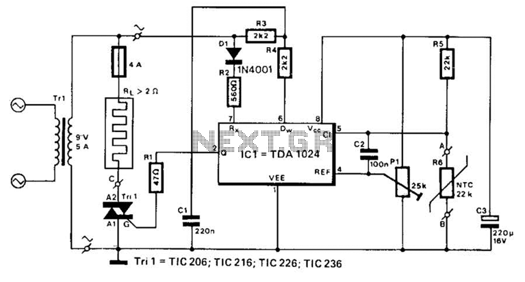
A TDA1024 electronic thermostat measures soil temperature using thermistor R6. The circuit employs zero-crossing switching to control the heater, which is constructed from elastic-coated steel wire. A potentiometer (PI) is utilized to adjust the temperature setting. The heater must...
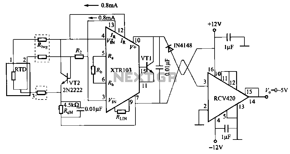
When the RTD temperature sensor is positioned far from the amplifier, the resistance of the sensor leads and their susceptibility to interference and other issues cannot be overlooked. The circuit shown in the figure addresses this problem. It utilizes...

FAN7710 Ballast Control circuit design for Compact Fluorescent Lamps electronic project. The FAN7710 is a specialized integrated circuit designed for the control of ballast systems in compact fluorescent lamps (CFLs). This circuit typically operates in a high-frequency range, facilitating efficient...
.png)
Gratitude is extended for the manual that was purchased; it is as described, enabling the continuation of work on the TV. The service will be utilized for all future manual needs. Thank you once again. Best regards, Lazlo. Most...
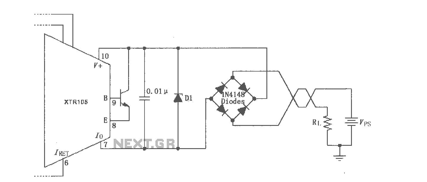
The XTR105 reverse voltage and over-voltage surge protection circuit is illustrated. A Zener diode rated at 36V can be utilized, with options including 1N4753A or 1N6286A. The maximum supply voltage (Vps) should be less than the minimum breakdown voltage...
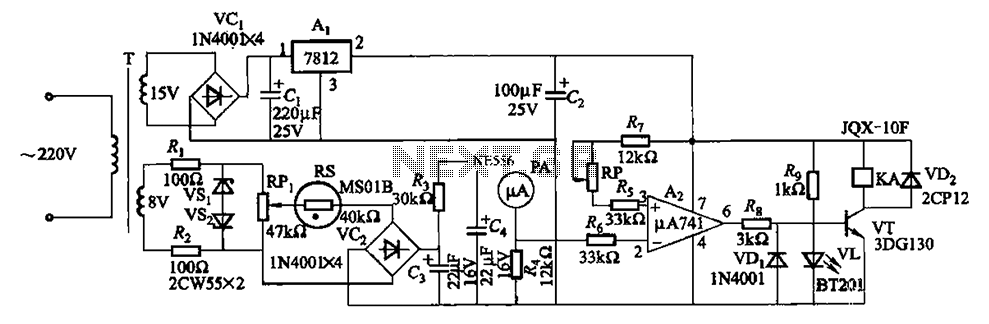
The humidity alarm system is based on integrated circuits and relays, utilizing the pA741 circuit. The MS01 employs a wet-type humidity resistance element as a probe. When the humidity exceeds a predetermined value, specifically set at 6 feet high,...