
Modem Off Indicator

The modem off indicator serves a crucial function for users who rely heavily on internet connectivity. This circuit is designed to provide a visual cue when the modem is powered off or not functioning, thereby preventing interruptions in internet usage.
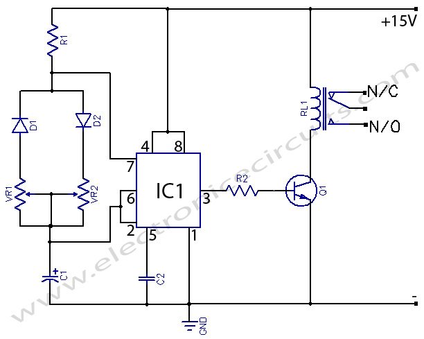
The basic components of the modem off indicator circuit typically include a light-emitting diode (LED), a resistor, and a power supply connected to the modem. When the modem is operational, the LED remains off, indicating that the modem is functioning correctly. Conversely, when the modem is powered down, the LED illuminates, signaling to the user that there is no active internet connection.
To construct this circuit, the LED is connected in series with a resistor to limit the current flowing through the LED, ensuring it operates within safe parameters. The resistor value can be calculated based on the supply voltage and the forward voltage drop of the LED, using Ohm's law.
For optimal performance, it is recommended to use a high-brightness LED to ensure visibility in various lighting conditions. Additionally, the circuit can be designed to integrate with the modem's power supply, allowing the indicator to function seamlessly without the need for an external power source.
Overall, the simplicity of the modem off indicator circuit does not detract from its effectiveness; rather, it highlights the importance of clear communication between the user and their internet connectivity status.The modem off indicator is intended especially for serious Internet surfers. It will be seen that the circuit of the indicator cannot be much simpler, or.. 🔗 External reference
Related Circuits

A low voltage frequency circuit utilizes the MAX630 for low battery voltage detection, functioning as an offset boost converter power supply. It is designed to maintain high efficiency (85%) while providing a DC output voltage of 5V at a...

In this project AT89S52 microcontroller is used for interfacing to various hardware peripherals. The current design is an embedded application, which will continuously monitor a moving Vehicle and report the status of the Vehicle on demand. For doing so...

This circuit utilizes a NE555 timer and a CD4020B. When +12 Vdc is applied to the circuit, the output of IC2 is set low via C2, which activates the relay and IC1, functioning as a pulse generator. IC1 generates...

Often, there is a need for an additional telephone ringer in an adjoining room to be alerted about incoming calls. For instance, if the telephone is situated in the drawing room, an extra ringer may be required in the...
555 Timer with On-Off Delay Circuit. This circuit utilizes the commonly available 555 integrated circuit (IC) to create a timer that allows for time adjustment in both on and off states. The 555 timer is a versatile device widely used...

When transistor Q1 is switched off, the circuit operates as a voltage follower. By applying a positive voltage to the emitter of Q1 through a 10 kΩ resistor, the transistor is activated and enters saturation. Consequently, the lower end...