
MOSFET LF2810 IC For 2W RF Amplifier Circuit diagram

The 2W RF amplifier circuit utilizing the M/A-Com LF2810A MOSFET is designed to amplify radio frequency signals efficiently. The LF2810A is a high-performance transistor capable of handling up to 10 watts of output power, making it suitable for various RF applications.
The circuit typically includes several key components: the MOSFET itself, biasing resistors, input and output matching networks, and power supply connections. The input matching network is crucial for maximizing power transfer from the source to the transistor, while the output matching network ensures that the amplified signal is efficiently delivered to the load, minimizing reflections and losses.
Biasing is essential to set the operating point of the MOSFET, ensuring it operates in the desired region of its characteristics for linear amplification. Resistors are used to establish the proper gate-source voltage, which controls the conduction of the MOSFET.
The overall design may also incorporate decoupling capacitors to filter out unwanted noise and stabilize the power supply, enhancing the amplifier's performance. Thermal management strategies, such as heat sinks, may be included to dissipate heat generated during operation, ensuring reliability and longevity of the circuit.
This type of RF amplifier circuit is commonly used in applications such as wireless communication systems, where signal integrity and amplification are critical for effective transmission and reception of radio signals.This circuit shows a 2W RF amplifier circuit . This amplifier is based on the M/A-Com LF2810A MOSFET. The transistor is actually a 10 watt, 28 .. 🔗 External reference
Related Circuits

A simple light-activated switch circuit with a diagram and schematic using IC LM311 wired as a voltage comparator and an LDR that acts as a light sensor. The described circuit utilizes the LM311 integrated circuit, which functions as a voltage...
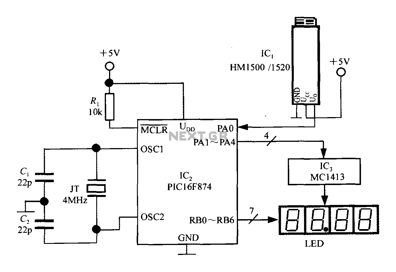
An intelligent humidity meter circuit utilizing the HM1500/1520 humidity sensor and a microcontroller configuration. The circuit operates on a +5V power supply and incorporates four common cathode LED digital displays. It employs three integrated circuits: IC1 is the HM1500/1520...
This is a 100 Watt inverter circuit designed with a minimal number of components. The circuit utilizes the CD4047 integrated circuit from Texas Instruments to generate 100 Hz pulses, and it employs four 2N3055 transistors to drive the load....
The circuit was intentionally designed without integrated circuits (ICs) and follows a traditional approach to achieve favorable harmonic distortion characteristics while avoiding the use of hard-to-find components. The amplifier can be powered conveniently using a 12V wall plug-in adapter....

The electric sewing machine saving circuit is designed with a Hall switch integrated circuit (IC) and a relay (K). When the switch is closed, power is activated. The circuit includes a resistor (R) and a capacitor (Ci) for RC...
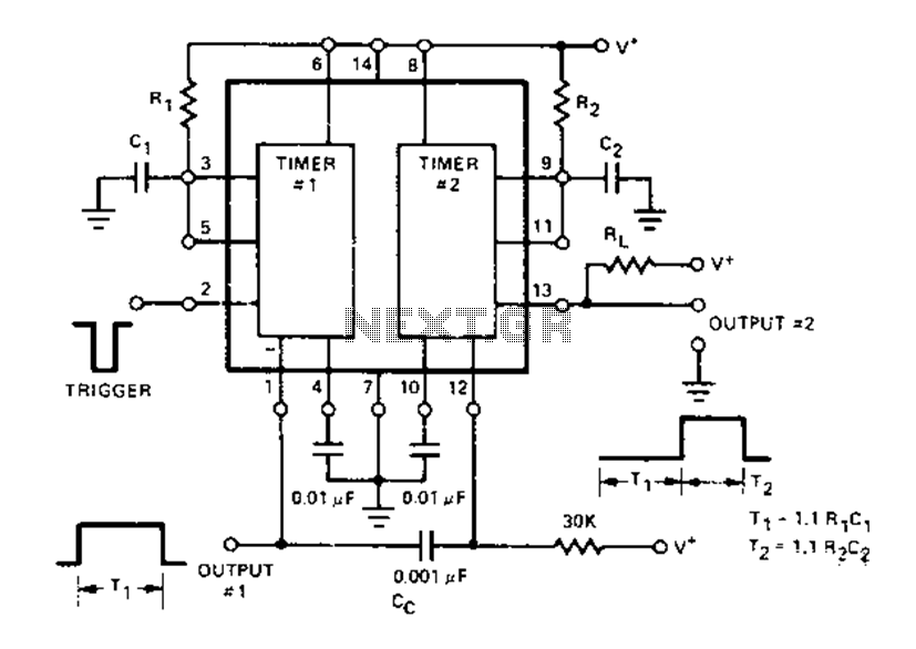
The Dual Timer Exar XR-2556 features a timing mechanism that can be triggered through capacitive coupling on a secondary timing pin. When a trigger input is engaged, the duration T1 can be set to 1.1R1C1, resulting in an increased...