
monitor life extender

The schematic for this circuit incorporates several essential components that work in tandem to monitor and control the temperature of the computer monitor effectively. The diodes D2, D3, and D4 are strategically placed to ensure accurate temperature sensing, and their negative temperature coefficient allows for precise adjustments in response to temperature changes. The use of shielded cables minimizes interference, which is crucial for maintaining the integrity of the temperature readings.
The power supply section, utilizing either the computer's existing power supply or an external adapter, ensures that the circuit operates reliably without introducing additional complexity. The decoupling capacitors C1 and C2 are vital for stabilizing the power supply, preventing fluctuations that could affect the performance of the temperature sensing and control circuitry.
The operational amplifiers IC1 and IC2 form the core of the control logic, with IC1 providing a stable reference voltage and IC2 processing the input from the temperature sensors. The integration network composed of R4 and C5 introduces a timed response to temperature changes, allowing for smoother transitions in fan operation and reducing the likelihood of sudden noise from abrupt on/off cycling.
The TLC555 timer IC3 is a versatile component that generates the sawtooth waveform necessary for PWM control. The design of the PWM output allows for fine-tuning of the fan speed based on the monitored temperature, optimizing cooling efficiency while minimizing energy consumption.
In conclusion, this circuit provides a robust solution for managing the thermal performance of CRT-type monitors, enhancing their longevity and reliability while contributing to energy conservation efforts. The careful selection of components and thoughtful design choices ensure that the circuit operates effectively under various conditions, making it an ideal addition for users with high-performance computing needs.This circuit was designed to protect a computer monitor from overheating. It is recommended to attach this circuit to power users` monitors! Most computer monitors of the CRT type fail owing to over-heating. After one or two hours of use, the rear of a monitor may become as hot as 45 degrees C, or 20 degrees above ambient temperature. Most heat co mes from the VGA gun drivers, the horizontal circuit, vertical circuit and power supply. The best possible way to extract heat and so prolong monitor life (and save the environment) is to add a brushless fan, which is lighter, energy-wiser and more efficient than a normal fan. In the diagram, diodes D2, D3 and D4 sense the monitor`s temperature. These diodes have a total negative temperature coefficient of 6 mV per degree Celsius. To eliminate noise, shielded wire should be used for the connection of the temperature sensor to the circuit sensor.
The +12-V supply voltage is borrowed from the computer`s power supply. Alternatively, a mains adapter with an output of 12 VDC may be used. C1 and C2 are decoupling capacitors to eliminate the ripple developed by switching or oscillation. R1 provides bias current to D1, a 6-V zener diode acting as a reference on the non-inverting pin of opamp IC2. B. IC1, a precision shunt regulator` raises the sensor diodes` voltage to just over 6 V depending on the adjustment of P1.
C4 is the decoupling capacitor with the sensor network. Integrator network R4-C5 provides a delay of about 3 seconds, transforming the on/off output signal of IC2. B into an exponentially decreasing or increasing voltage. This voltage is fed to pin 3 of the second opamp, IC2. A. The hard on/off technique would produce a good amount of noise whenever the load is switched, hence an alternative had to be found.
IC3, a TLC555, is used as an astable multivibrator with R5 and C6 controlling the charging network that creates a sawtooth voltage with a frequency of about 170 Hz. This sawtooth is coupled to pin 2 of IC2. A, which compares the two voltages at its input pins and produces a PWM (pulse-width modulated) output voltage.
The sawtooth wave is essential to the PWM signal fed to power output driver T1 by way of stopper resistor R6. The power FET will switch the fan on and off fan according to the PWM drive signal. The back emf pulses that occur when T1 switches on and off are clamped by a high-speed diode, D7. Initially, turn P1 to maximum resistance. Blow hot air from a hair dryer onto the sensor-diodes for a minute or so, then get the temperature meter near the sensor diodes and adjust P1 slowly towards the minimum resistance position with a digital meter hooked up on pin 7 of IC2.
B. Roughly calibrate the temperature to 40 degrees C. At this temperature, the meter will show approximately 12V. The circuit will draw about 120mA from its 12-V supply. 🔗 External reference
Related Circuits

The ECM circuit comprises four sections, as illustrated in the block diagram. A power converter generates a voltage that correlates with the actual real power consumed by the load. This voltage supplies both a bar graph and a voltage-to-pulse...
This is a circuit diagram for a fuse monitor circuit indicator. This very simple circuit utilizes only two components: a single resistor and an LED. This circuit provides a visual indication when the fuse has blown. LED1 typically remains...

The portable hypoxia monitoring circuit comprises the oxygen sensor OS-12, a DC amplifier IC1, an A/D converter IC4, and a liquid crystal display F2100-34PI. Additionally, it includes a voltage comparator IC2 and a positive and negative power converter IC,...
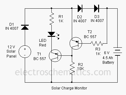
This add-on circuit can be attached to the solar charger to indicate whether the battery is charging. It lights a red LED to signal that the battery is charging. The described add-on circuit serves as a visual indicator for the...
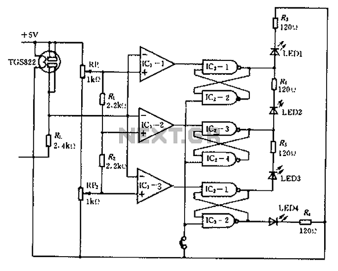
Ceramic gas sensors can be utilized to analyze the content of alcohol vapor. With the appropriate sensor circuit, it is possible to detect blood alcohol content. The operating principle is straightforward: if blood alcohol content is present in a...
A thermistor placed in the specified position creates a heat-activated sensor. Variations in temperature will modify the output of the operational amplifier (op-amp), activating the relay and illuminating the LED. Interchanging the positions of the thermistor and the 47k...