
Simple Fuse Monitor Indicators

The fuse monitor circuit is designed to provide a straightforward method for detecting fuse failures within an electrical system. The circuit operates using minimal components, which enhances reliability and reduces the likelihood of component failure. The primary components involved in this circuit are an LED (LED1) and a current-limiting resistor (R1).
When the fuse (F1) is intact, the circuit remains in a normal operating state, and the LED remains off, indicating that the electrical path is complete and functioning correctly. However, if the fuse blows due to an overload or short circuit, the circuit configuration changes. The blown fuse creates a short circuit condition, allowing current to flow through the LED. As a result, LED1 illuminates, providing a clear visual indication that the fuse has failed and requires replacement.
The resistor (R1) plays a crucial role in this circuit by limiting the current flowing through the LED when it is illuminated. This current-limiting feature is essential to prevent damage to the LED due to excessive current. The value of R1 must be chosen carefully to ensure that it allows sufficient current to illuminate the LED while remaining within the safe operating limits of both the LED and the power supply.
This circuit can be implemented in various applications where fuse monitoring is critical, such as in power distribution panels, automotive systems, and consumer electronics. Its simplicity and effectiveness make it an ideal solution for providing immediate feedback on the status of fuses, enhancing safety and maintenance efficiency.This is a circuit diagram fuse monitor circuit indicators. This very simple circuit uses only two components, but only with a single resistor and LED this circuit provides visual indication when the fuse has blown. LED1 is usually dead, a short circuit by the fuse, F1. Please note that the LED will only illumininatet in damaged condition, ie with a short circuit or shunt the load.
In this case the current is reduced to a safe level by R1 🔗 External reference
Related Circuits
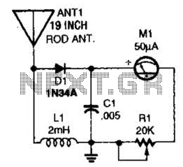
This basic field-strength meter offers an affordable solution for monitoring an amateur radio or CB transmitter, as well as an antenna system, to ensure maximum output. The field-strength meter is designed to measure the strength of radio frequency (RF) signals...
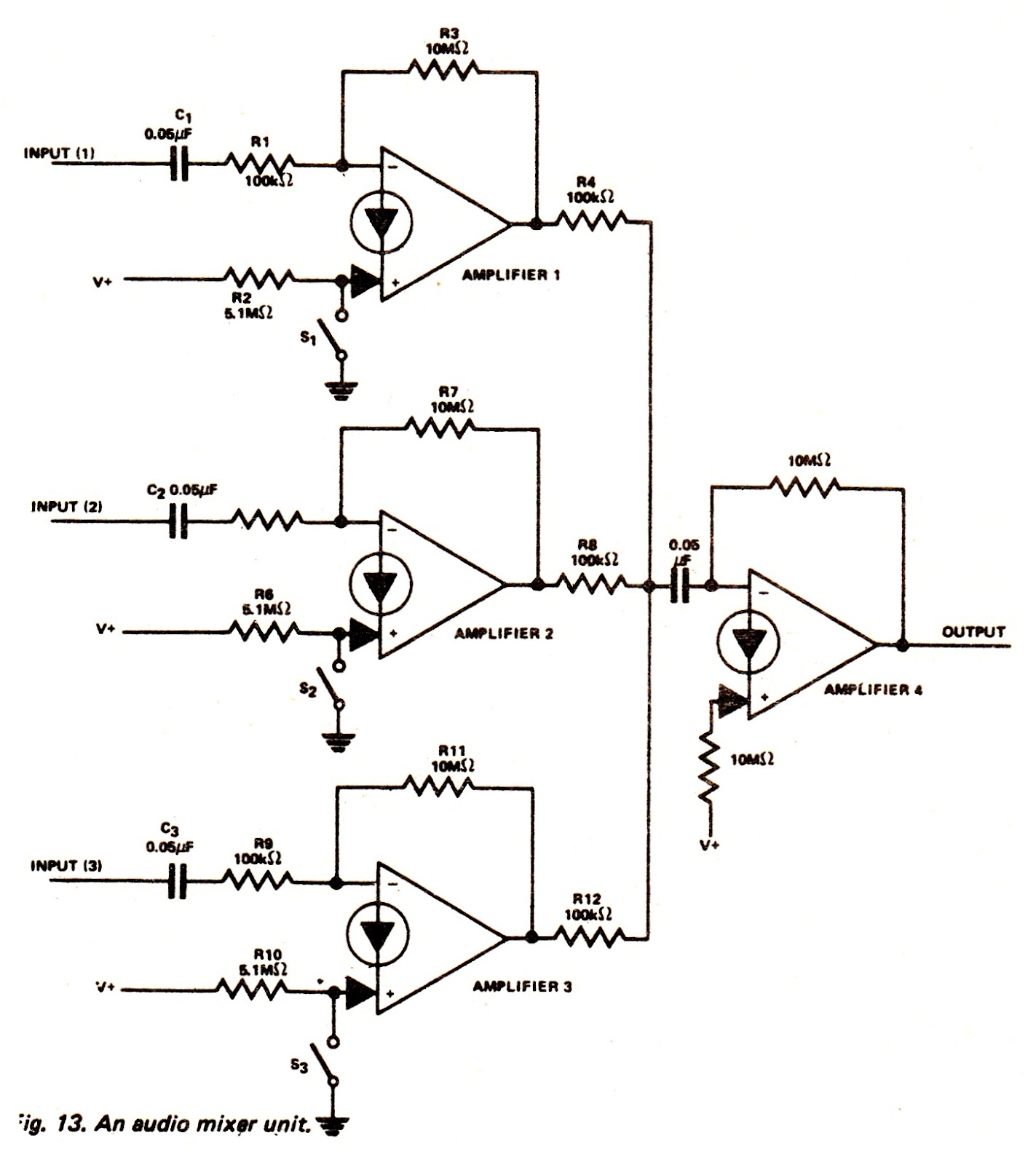
The amplifiers of an LM3900N device can be utilized to create an audio mixer unit that allows for the combination of three separate audio signals into a single composite output. The audio mixer circuit provided operates with a single...

The typical BPM range for music is between 40 and 240 BPM, corresponding to periods of 1500 ms and 200 ms, respectively. A BPM of 120 equates to a period of 500 ms. The circuit requires a resistor R4...
This is a simple phono preamplifier circuit diagram. In recent years, following the introduction of CDs, vinyl recordings have almost disappeared. Nevertheless, a phono preamplifier remains useful for listening to old vinyl discs from a well-preserved collection. This simple...
In the first circuit, the BC548 transistor is configured as a Colpitts oscillator, with the frequency being adjusted through the insertion of a crystal. A high-quality crystal will generate high-frequency oscillations, and the output at the collector is rectified...
While many power supplies can be set to limit their output current to a defined level to protect the circuit they are powering, no such protection is available. To enhance the safety and reliability of electronic circuits, it is crucial...