
Mono to stereo audio generator
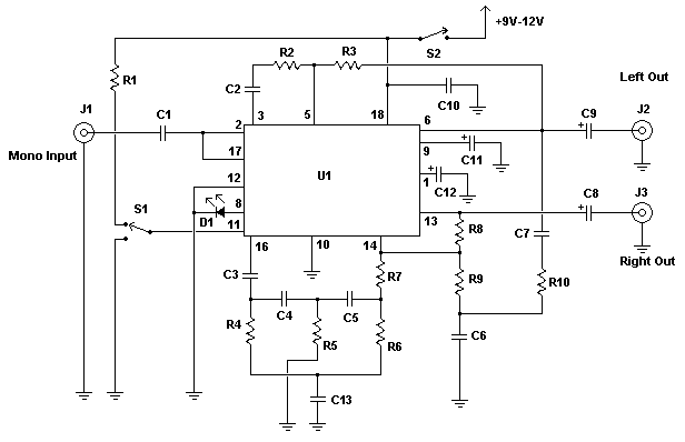
This circuit is designed to enhance mono audio sources by creating a simulated stereo effect. The core principle involves manipulating audio signals through frequency shifting, which tricks the auditory perception into interpreting the sound as stereo, even though it originates from a mono source.
The schematic consists of various resistors (R1 to R10) and capacitors (C1 to C12) that form a network for signal processing. The resistors are selected to create a specific impedance and voltage divider network that influences the audio signal's characteristics. For instance, R1 (4.7K) and R2 (10K) are positioned to manage the initial signal levels, while R5 (11K, 1%) provides precise control over the output signal.
Capacitors are utilized for coupling and decoupling signals, with C1 (0.1uF) and C2/C3 (0.47uF) playing crucial roles in filtering specific frequency ranges to achieve the desired stereo effect. The combination of various capacitor values allows for fine-tuning the frequency response of the circuit, ensuring that the illusion of stereo sound is convincing.
The TBA3810 integrated circuit (U1) serves as the primary audio processing unit, responsible for the frequency shifting and synthesis of the stereo output. It is connected to the audio input and output jacks (J1, J2, J3), which are typically RCA connectors, allowing for easy interfacing with standard audio equipment.
The circuit includes two switches: S1 (an SPDT switch) and S2 (an SPST switch). S2 controls the power supply to the circuit, providing the ability to turn the circuit on or off. S1 enables the user to toggle between the processed stereo output and a direct mono output, allowing for comparison and flexibility in usage.
Powering the circuit requires a well-filtered 9V-12V source, such as a standard 9V battery, ensuring low current draw and efficient operation. The inclusion of an LED (D1) provides visual feedback for the circuit's operational status.
Overall, this circuit is an effective solution for enhancing mono audio sources, making it suitable for applications where stereo sound is desired without the complexity of true stereo signal processing.This circuit attempts to liven up mono sound sources by simulating a stereo signal. It does this by shifting certain frequencies between left and right to fool the ear. It can often produce a passable mock stereo sound to bring some depth to otherwise flat recordings. Of course, there is no way to produce real stereo sound from a purely mono source unless the synthesizer had a way to tell which direction the original sound came from, but an illusion is generally enough for all but the hard core audiophile. R1 1 4.7K 1/4W Resistor R2 1 10K 1/4W Resistor R3 1 12K 1/4W Resistor R4, R6 2 22K 1/4W Resistor R5 1 11.K 1% 1/4W Resistor R7 1 16K 1/4W Resistor R8 1 100K 1/4W Resistor R9 1 24K 1/4W Resistor R10 1 18K 1/4W Resistor C1 1 0.1uF Ceramic Disc Capacitor C2, C3 2 0.47uF Ceramic Disc Capacitor C4, C5, C7 3 0.01uF Ceramic Disc Capacitor C6 1 0.013uF Ceramic Disc Capacitor C8, C9 2 4.7uF 25V Electrolytic Capacitor C10 1 0.22uF Capacitor C11 1 47uF 25V Electrolytic Capacitor C12 1 100uF 25V Electrolytic Capacitor D1 1 LED (Red, Green or Orange) U1 1 TBA3810 (442-794) S1 1 SPDT Switch S2 1 SPST Switch J1, J2, J3 3 RCA Jack Other suitable jack MISC 1 PC Board, Wire, Case, Holder for D1, Socket for U1 This circuit was sent in by oRbEq (email address unavailable). S2 controls power to the circuit. Switching S1 to ground bypasses the circuit and outputs mono sound to both output jacks. Setting S1 to R1 enables the synthesized stereo sound at the outputs. The circuit draws very little current and can thus be powered by most any well filtered 9V-12V source (including a standard 9V radio battery).
🔗 External reference
Related Circuits
This design is based on an 18 Watt audio amplifier and was developed primarily to meet the needs of users who are unable to find the TLE2141C chip. It utilizes the widely available NE5532 dual integrated circuit; however, its...
If you want to build one yourself, you have to get two audio transformers which have 1:1 transformation ratio and greater than 1 kohm impedance. There are high quality audio transformers in the markets that meet those specs, but...
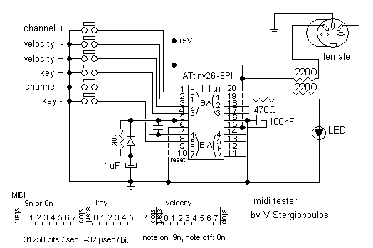
This circuit based on ATtiny26 but it could be anyone microcontroller of AVR family. Produce stable one MIDI tone and you can change it by press some keys like to change midi channel 0-15, velocity 0-127, pitch 0-127. It...
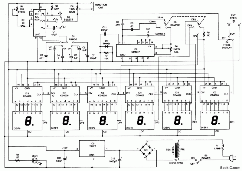
This circuit generates sine, square, and triangle waves ranging from 0.1 Hz to 1 MHz. It includes a counter that measures the frequency of the function generator or an external signal with a peak-to-peak voltage of a few volts,...
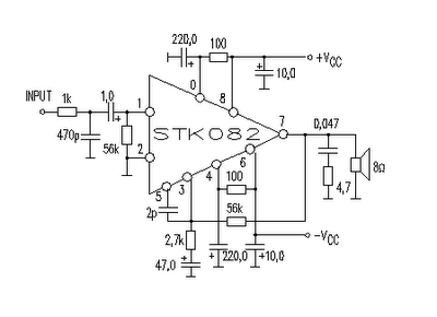
This amplifier circuit is suitable for home power audio devices. The STK082 amplifier specifications suggest that it can operate with supply voltages of up to ±43V. However, it is advisable to use no more than ±25V for 8-ohm loads,...
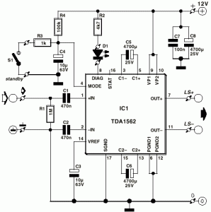
A car audio amplifier utilizing the TDA1562Q, capable of delivering 50W of audio power. The circuit diagram includes two resistors of 1 kOhm and two resistors of 4.7 kOhm. The TDA1562Q is a high-performance integrated circuit designed for car audio...