
water activated alarm

The described circuit utilizes a transistor as a sensing element in a moisture detection system. In its default state, the transistor remains off, preventing current flow and thereby keeping the alarm inactive. The critical component of this design is the moisture-sensitive probes, which, when exposed to water, initiate the conduction of the transistor. This conduction allows current to flow through the alarm circuit, effectively signaling the presence of moisture.
The inclusion of an On/Off switch provides the user with control over the operation of the circuit, enabling it to be deactivated when not in use. The choice of probe materials is crucial for the longevity and reliability of the system. Non-reactive metals such as gold or silver are preferred due to their resistance to corrosion and oxidation, which can affect conductivity over time. However, in cost-sensitive applications, copper strips can serve as a viable alternative. While copper is prone to oxidation, the low current in the circuit mitigates the potential impact of increased resistance.
The emitter follower configuration of the transistor allows for a direct connection to the load while maintaining a high input impedance. This configuration eliminates the need for a base resistor, as the transistor's operation is primarily determined by the emitter's impedance. The oscillator circuit connected to the emitter limits the current flowing through the transistor, ensuring safe and efficient operation.
Overall, this moisture detection circuit is designed for simplicity and effectiveness, making it suitable for various applications where water presence needs to be monitored. Proper selection of materials and circuit configuration enhances reliability and performance, making it an effective solution for moisture detection.Under dry conditions, the transistor will have no bias current and be fully off. However as the probes get wet the transistor will conduct and sounding the alarm. An On/Off switch is provided and remember to use a non-reactive metal for th e probe contacts. Gold or silver plated contacts from an old relay may be used, however a cheap alternative is to wire alternate copper strips from a piece of veroboard. These will eventually oxidize over but as very little current is flowing in the base circuit, the higher impedance caused by oxidization is not important.
No base resistor is necessary as the transistor is in emitter follower, current limit being the impedance at the emitter (the oscillator circuit). 🔗 External reference
Related Circuits

The Touch Alarm circuit is commonly utilized for security purposes and is typically installed on doors. Its advantages include low cost and difficulty in detection by burglars or intruders. An example of a touch alarm circuit is designed by...

The design is based on Silicon Chip's PIC-Based Water Tank Level Meter. Instead of programming PICs, an Arduino was prototyped, and the final version was built using PICAXE microcontrollers. An MPX-2010DP silicon pressure sensor, which is temperature compensated and...

This low-cost burglar alarm utilizes a 12V strobe light and a truck reversing horn as the visible and audible outputs, respectively, while the alarm system operates on a 12V power supply. The burglar alarm circuit is designed to provide an...
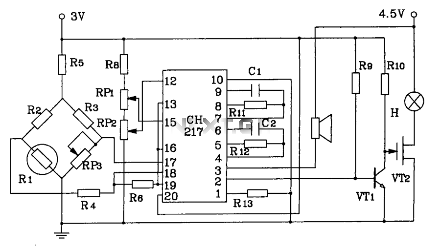
CH217 is a monolithic gas detection alarm integrated circuit. The gas detection alarm circuit diagram includes R1 as the gas sensing probe, where the resistance increases as the gas concentration decreases linearly. RP3 is used to adjust the output...

This is a compact circuit that can be wired in parallel with existing switches. The device enables one or more lamps to illuminate at sunset and turn off at dawn. It incorporates components Q1 and Q2. The circuit is designed...

The following circuit illustrates a BC 547 transistor used in a garage alarm sensor circuit diagram. Features include a simple single-zone burglar alarm circuit. The BC 547 transistor is a popular NPN bipolar junction transistor (BJT) that is frequently used...