
Motorcycle Alarm No.1 - Construction Guide

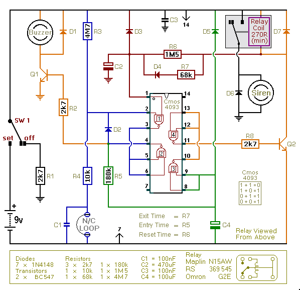
The circuit operates primarily through a relay-based latching mechanism. The relay serves as the main actuator for the siren, while the transistors function as signal amplifiers and control elements. Upon the closure of the normally-open switch, D1 plays a crucial role in ensuring that the relay coil receives the necessary ground connection for energization. The forward biasing of Q1 allows for the charging of C1, which is pivotal in maintaining the relay's state even after the switch is opened.
The modified Darlington Pair configuration formed by Q2 and Q3 enhances the input impedance significantly, allowing for a slower discharge of C1. This characteristic is essential for applications where prolonged activation of the relay is desired. The discharge path through R4 and the base-emitter junctions of Q2 and Q3 ensures that the relay remains engaged until the voltage across the coil drops below a critical threshold.
To further optimize the circuit, the inclusion of R1 ensures that Q1 remains off during standby, preventing unintended activation due to environmental factors such as moisture. The careful selection of resistor values, particularly R2 and R3, ensures that the circuit operates within safe limits while providing the necessary functionality.
Protection diodes D2 and D3 serve a vital role in safeguarding the circuit against inductive kickback from the relay coil, which can generate harmful voltage spikes. This protective measure is essential in ensuring the longevity and reliability of the overall circuit, particularly in environments where other sensitive electronics may be connected.
In summary, this circuit design effectively utilizes a relay, transistors, and capacitors to create a latching alarm system that is both efficient and reliable, with built-in protections to ensure safe operation in various conditions.When one of the normally-open switches is closed - two things happen. Firstly - the negative side of the relay coil is connected to ground through D1. This causes the relay to energize. And the relay in turn sounds the siren. = Secondly - the emitter-base junction of Q1 is forward-biased. The transistor switches on - and current through R3 and Q1 charges C1. C1 is part of the latching circuit that keeps the relay energized after the trigger-switch has been re-opened. = When the switch is re-opened - and Q1 switches off - the charge stored in C1 keeps Q2 switched on. Q2 in turn keeps Q3 switched on. Q3 connects the negative side of the relay coil to ground. So the relay remains energized and the siren continues to sound. It will continue to sound until C1 discharges through the base-emitter junctions of Q2 and Q3. = The length of time the relay remains energized depends on the value of C1 - and the input impedance (resistance) of Q2 and Q3.
A single transistor has a relatively low input impedance - so C1 would discharge quickly. But Q2 and Q3 are connected to form a modified Darlington Pair. The input impedance of a Darlington Pair is very high. Roughly that of the single transistor - squared. And R4 increases it even further. So C1 discharges relatively slowly through the two base-emitter junctions. The precise time it takes depends on the characteristics of the actual components used - particularly the gain (hfe) of the transistors. = As C1 discharges - the current through R4 and Q2 falls. So the base current through Q3 falls also. This causes the Q3 collector-emitter voltage to rise. As it does so - the voltage across the relay coil falls. When the voltage across the relay coil falls to a sufficiently low level - the relay drops out and the alarm resets.
= However - although they can no longer keep the relay energized - Q2 & Q3 would continue to conduct to some degree. This would waste energy - and lead to an increased standby current. To prevent this from happening - the base of Q2 is connected to the normally-closed contact of the relay.
When the relay drops out - the base of Q2 is taken to ground. This completes the discharge of C1 - and turns Q2 & Q3 firmly off. In this condition the standby current is virtually zero. = R1 connects the base of the pnp transistor to the positive line. This keeps Q1 switched off in standby mode. If R1 had a very high value - moisture on the trigger-switches might tend to turn Q1 on. And current through the transistor would flow to ground through the normally-closed relay contacts. This would cause a substantial increase in standby current. The value of 1k was chosen for R1 - in order to keep Q1 switched firmly off. = When charged - the voltage across C1 is about 1v2 to 1v4. This limit is set by the base-emitter junctions of Q2 and Q3. If R2 were not present then the collector-base junction of Q1 would hold C1 at 0v6 to 0v7. This would prevent the capacitor from reaching a high enough potential to switch Q2 and Q3 on. The value of R2 is not very critical. I choose 4k7 - but any value that turns Q1 on and holds its base above about 2-volts will do. R3 limits the surge current through Q1 as C1 charges. = The only transistor with any real work to do is Q3. If the relay has a coil resistance of at least 270 ohms - then the maximum current passing through Q3 will be 12 G· 270 = 45mA. The BC547 has an Ic(max) of 100mA. = Relay coils and some sounders produce high reverse-voltage spikes that will destroy sensitive electronic components.
D2 and D3 are there to short-circuit the spikes before they can do any damage. Although there is nothing in the alarm circuit itself that`s likely to be damaged - I have no idea what other electronic equipment might be connected to the same supply. So I included the two diodes as a precaution. = If the alarm switches are fitted properly - the circuit should reset a minute of two after the bike has been
🔗 External reference
Related Circuits
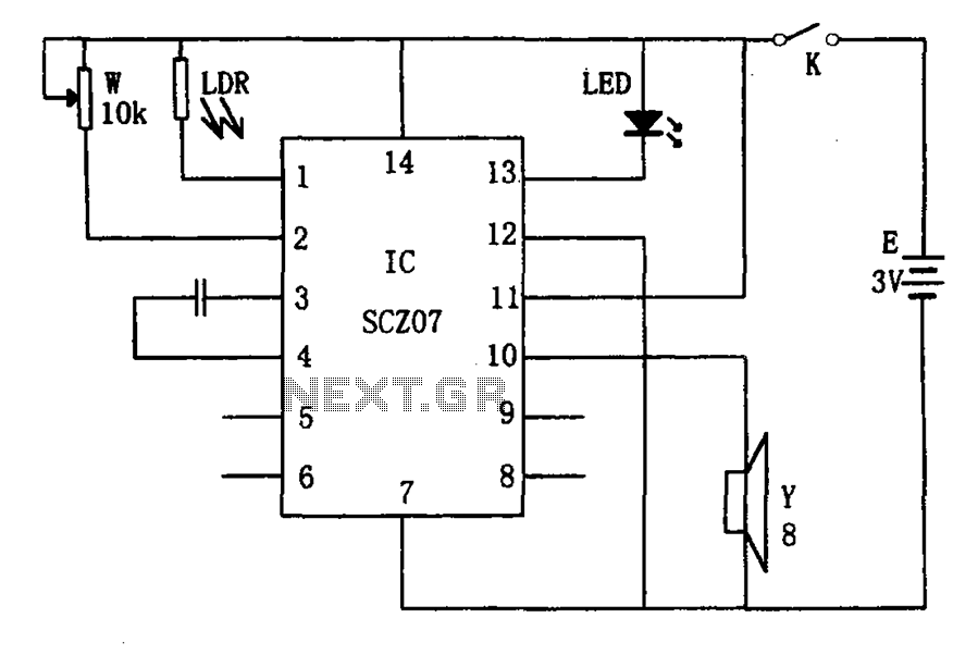
The weak light alarm circuit is illustrated in the figure. The oscillator circuit's core component is the SCZ07. The input signal is controlled by a potentiometer (W) and the output signal is processed by a photoresistor (LDR). The circuit...

Infrared Intruder Alarm Circuit. This circuit alerts the presence of a trespasser using an infrared system or Infrared Intruder Alarm circuit, which is quite interesting. It activates when there is an intrusion detected. The Infrared Intruder Alarm circuit operates by...

When the water boils, it not only triggers the police but also cuts off the heater power. A temperature sensing element is integrated with a fluorescent neon light bulb, which is restructured within the starter. The described circuit features a...

This circuit employs a thin piezoelectric sensor to detect vibrations caused by knocking on a surface, such as a door or table. It amplifies and processes the sensor's signal to trigger an alarm for a predetermined duration. The piezoelectric...
This is an enhanced version of the simple Garage/Shed Alarm. The entry and exit delays have been increased to approximately 30 seconds, and a timed siren cut-off and automatic reset have been added. The LED has been replaced with...

Inverters Ula and Ulb are connected in a simple RC oscillator circuit. The frequency is determined by the values of R1, C1, and C2, as well as the internal characteristics of the integrated circuit. While the circuit is oscillating,...