
moving message display

The schematic for this circuit integrates several key components that facilitate the operation of the LCD display. The ATmega16 microcontroller serves as the central processing unit, executing the control logic and managing the communication with the LCD. The connection between the microcontroller and the LCD is made through both data and control lines, ensuring accurate data transfer and command execution.
The power supply section is critical, as it converts the high voltage AC mains to a stable low voltage DC required for the operation of digital electronics. The step-down transformer reduces the voltage, while the bridge rectifier converts AC to DC. The capacitor smooths the rectified output, and the 7805 voltage regulator ensures that the output voltage remains constant at 5V, which is essential for the reliable operation of the microcontroller and the LCD.
The use of the HD44780 controller allows for flexible interfacing options, supporting both 4-bit and 8-bit data modes. This flexibility enables the designer to optimize the number of GPIO pins used based on the specific requirements of the application. The timing diagram provides insight into the operation of the control signals, ensuring that the correct sequence of operations is followed for successful data transmission.
In summary, this project exemplifies the integration of microcontroller technology with LCD display systems, showcasing the capabilities of the AVR architecture and the versatility of the HD44780 controller in practical applications. The combination of these components results in an efficient and effective moving-message display system.You can make an LCD show a brief moving message by interfacing it to a microcontroller. Here`s an AVR-based moving-message display that uses a 16G—2 LCD display incorporating HD44780. The 16G—2 LCD can display 16 characters per line and there are two such lines. Fig. 1 shows the circuit for AVR ATmega16-based moving-message display on an LCD. It consists of an ATmega16 microcontroller, a 16G—2 LCD, an SPI6 connector and a power supply section. To derive the power supply for the circuit, 230V AC mains is stepped down by a 9V, 250mA secondary transformer, rectified by bridge rectifier module BR1A and filtered by capacitor C1.
The voltage is regulated by a 7805 regulator. LED1 glows to indicate the presence of power in the circuit. The regulated 5V DC powers the entire circuit including SPI6 connector. Port-C pins PC4 through PC7 of the microcontroller (IC2) are connected to data lines D4 through D7 of the LCD. The LCD control lines ”read/write (R/W), register-select (RS) and enable (E) ”are connected to PD6, PC2 and PC3 of IC2, respectively.
Why AVR microcontroller AVR is faster and more powerful than 8051 microcontroller, yet reasonably cheaper and in-circuit programmable. Most AVR development software are free as these are Open Source. Moreover, discussions and tutorials on the AVR family of processors are available on the Internet. ATmega16 is a high-performance, low-power 8-bit AVR microcontroller. It has 16 kB of in-system self-programmable flash, 1 kB of internal SRAM, 512 bytes of EEPROM, 32G—8 general-purpose working registers and JTAG Interface (which supports programming of flash, EEPROM, fuse and lock bits).
The project uses a Hitachi HD44780-controlled LCD module. The HD44780 controller requires three control lines and four or eight input/output (I/O) lines for the data bus. The user may choose to operate the LCD with a 4-bit or 8-bit data bus. If a 4-bit data bus is used, the LCD will require a total of seven data lines ”three lines for sending control signals to the LCD and four lines for the data bus.
If an 8-bit data bus is used, the LCD will require a total of eleven data lines ”three control lines and eight lines for the data bus. The enable control line is used to tell the LCD that the microconroller is sending the data to it. To send data to the LCD, first make sure that the enable line is low (0). When other control lines are completely ready, make enable pin high and wait for the LCD to be ready.
This time is mentioned in the datasheet and varies from LCD to LCD. To stop sending the data, bring the enable control low (0) again. Fig. 2 shows the timing diagram of LCD control lines for 4-bit data during write operation. When the register-select line is low (0), the data is treated as a command or special instruction (such as clear screen and position cursor). When register-select is high (1), the text data being sent is displayed on the screen. For example, to display letter L` on the screen, register-select is set to high. When the read/write control line is low, the information on the data bus is written to the LCD. When read/write is high, the program effectively queries (or reads) the LCD. This control command can be implemented using C` programming language. For 4-bit interface data, only four bus lines (D4 through D7) are used for data transfer. Bus lines D0 through D3 are disabled. The data transfer between HD44780 and the microcontroller completes after the 4-bit data is transferred twice.
Controlling a standard numeric LCD is not that difficult. To display text on the LCD, correct library files for the LCD are needed. Many LCD libraries are available on the Internet, which are used in various applications. You may get confused which library is suitable for your application. This project demonstrates sending the text to th 🔗 External reference
Related Circuits
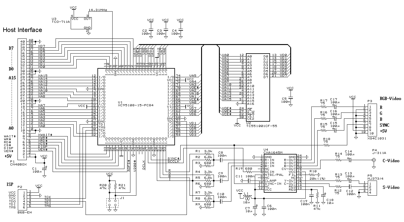
This is a simple display controller. It can be controlled with a small microcontroller, such as MCS51, 68HC11, Z80, AVR, and others. Several years ago, I found an article that controlling a TV with only a PIC microcontroller, and...
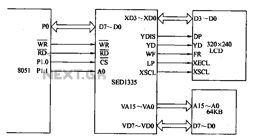
The MCS-51 series single-chip interface circuit 8051 is utilized to control the SED1335 35 dot matrix LCD display. This controller can manage up to a 640x256 dot matrix LCD display for both graphics and character representation, with the capability...
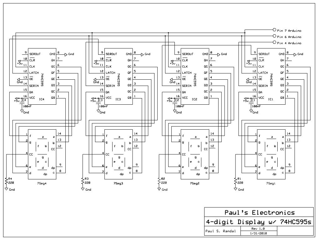
Four 595 shift registers are used together to drive 7-segment displays, with additional code implemented to accept input from a PC. Unlike the previous design that utilized 10-LED bar graphs, the current configuration employs 7-segment displays, which present a...
The game-scoring display screen circuit diagram is depicted in the image above. The circuit consists of an add/subtract scoring input circuit, an add/subtract scoring circuit, a counting-decoding display circuit, and a reset circuit. The game-scoring display circuit is designed to...
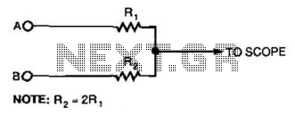
This simple resistor circuit can be used to trick an oscilloscope into displaying two logic signals on one channel. By selecting R2 to be twice the value of R, the oscilloscope trace will show one of four distinct analog...
Liquid-crystal displays (LCDs) are available in various sizes and configurations, including their pinouts. Many of these displays require the manufacturer's documentation for proper usage, which is often difficult to locate when needed. Consequently, a small tester designed to identify...