
MRC DCC Decoder

The AD322 DCC decoder is designed for G-Scale model trains, facilitating digital control over locomotive functions. It operates at a maximum current of 8 amps, making it suitable for powering larger models. The decoder supports multiple functions, including sound, lighting, and motor control, enabling intricate operation and customization of model trains.
For users interested in enhancing the functionality of the AD322, the addition of reed switches is a practical modification. These switches can be activated by magnets placed on the track, allowing for the triggering of sound functions such as bells or horns without the need for a DCC controller that supports these features. This modification can significantly enhance the realism of train operations, especially in layouts where sound effects are desired but not supported by the existing control system.
The pin configuration of the AD322 is essential for users intending to modify or troubleshoot the decoder. Each pin serves a specific function, and understanding their roles is crucial for effective repurposing. Pin 1, located in the upper right corner, is a reference point for counting the pins. The top row consists of pins 1 through 10, arranged from right to left, while the bottom row contains pins 11 through 20, arranged from left to right. Utilizing an oscilloscope to test each pin can provide insights into the operational status and functionality of the decoder, allowing users to identify which pins correspond to specific functions.
Overall, the AD322 DCC decoder presents a versatile platform for model train enthusiasts looking to customize their layouts, offering opportunities for both functional enhancement and creative modifications.The AD322 is an 8 amp G-Scale DCC decoder. The notes below may be of benefit to owners who wish to understand or repurpose ("hack") the decoder. It has a rather full set of functions that could easily be repurposed for a number of other projects.
One modification that comes to mind is to add two reed switches so that magnets on the track can trigg er the bell and/or horn. This would be valuable for those who don`t have those functions on their DCC Controller. By testing each pin with an oscilloscope I gleaned the following by cycling through various functions on the board. Note that pin 1 is in the upper right corner in the photo - next to the small round dimple. Pins are counted 1-10 from right to left for the top row and 11-20 from left to right across the bottom.
🔗 External reference
Related Circuits
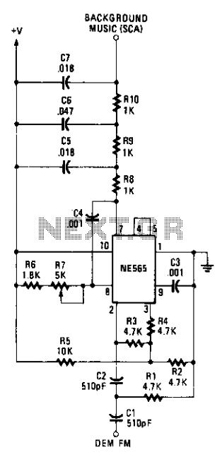
The circuit employs a Signetics NE565 Phase-Locked Loop (PLL) as a detector to recover the SCA signal. The input to the SCA decoder circuit is connected to an FM receiver at a point between the FM discriminator and the...
This is an image Schematic. No Description available. The provided input indicates that there is a schematic image, but no additional descriptive information is available regarding its components, functionality, or application. In the context of electronic schematics, such images...
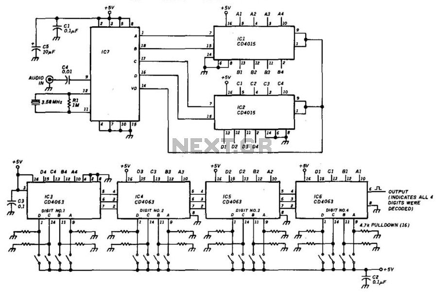
This decoder will respond to a preselected 4-digit DTMF number. IC7 is a Radio Shack IC device (part #276-1303). The logic is all CMOS. The digits are selected by SW1 and SW2, a pair of 8-position DIP switches. The described...
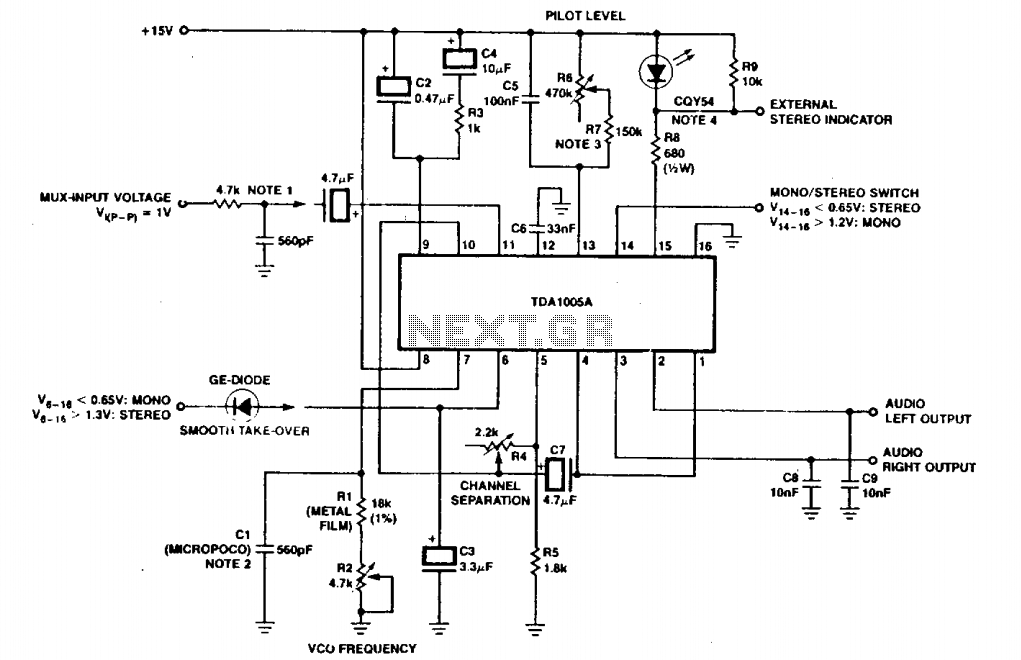
The circuit depicted includes an RC filter (Figure T). The micropico capacitor has a temperature coefficient of 125 x 10^-6 at 60 x 10^-6°C. In simplified circuits, a fixed resistor, such as 620kΩ, can be utilized to ensure a...
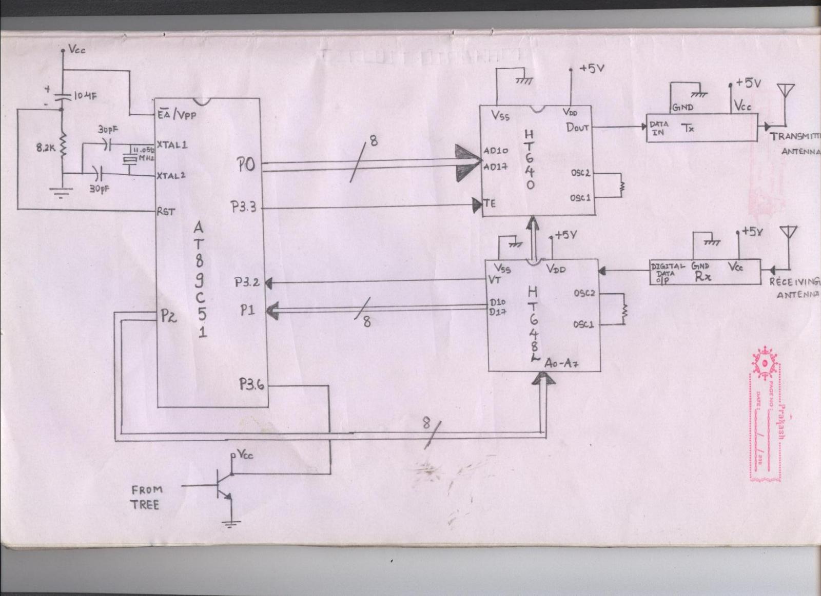
The issue arises when connecting the 8051 microcontroller to the HT640 encoder; the data transmitted is not received by the receiver. However, when the 8051 connections are removed, the transmission functions correctly. This indicates that manual RF communication works...
The decoder is intended to be a reference quality prototype with maximum flexibility for experimental use with different speaker layouts. A new improved version has been added at the end. There are two main sections to the instrument. The...