
Multi Channel Remote Control System

The multi-channel remote control system is designed to facilitate the wireless operation of multiple appliances, making it an ideal choice for hobbyists and DIY enthusiasts. The RF transmitter module sends encoded signals to the RF receiver, which interprets the commands and activates the appropriate relay. Each relay corresponds to a specific appliance, allowing for individual control.
The HT12E encoder is responsible for transforming the push-button inputs into a serial data stream. This is achieved through its parallel-to-serial conversion capabilities, where each button press generates a unique binary code that represents the specific device to be controlled. The output from the encoder is transmitted via RF waves, which are received by the HT12D decoder. The decoder then converts the received serial data back into parallel format, triggering the corresponding relay.
The relay acts as a switch, controlling the power to the connected appliances. When a button on the transmitter is pressed, the relay closes, allowing current to flow to the appliance. The subsequent press of the same button opens the relay, cutting off the power supply. The load current capacity of the relay must be selected based on the requirements of the appliances being controlled to ensure safe and effective operation.
Powering the circuit requires a stable 5V supply, which is critical for the reliable functioning of the ICs involved. Voltage regulators may be necessary if the power supply fluctuates. The use of RF technology in this circuit offers significant advantages over infrared systems. RF signals can penetrate obstacles, allowing for control from different rooms or even outdoors, and do not require direct line-of-sight alignment.
In summary, this multi-channel remote control circuit provides a versatile and efficient means of managing multiple appliances wirelessly, leveraging the capabilities of RF communication and ensuring ease of use through simple push-button controls.Here is a hobby circuit of a multi channel remote control system, by which you can control 8 different appliances. The main sections of this multi channel remote control circuit are the RF receiver and transmitter. By using this circuit we can control 8 devices, each of them independently by pressing the push buttons.
When the button is pushed, co rresponding relay is turned ON and is turned OFF on the next push. Here the relay load current is dependent on the relay used. A serial encoder IC HT12E and a serial decoder IC HT12D are used, where the encoder IC encodes the parallel data to serial and decoder IC decodes the serial data to parallel during the wireless transmission. You must need a regulated power supply of 5 volt for this circuit because ICs 7476 and 74138 requires 5v for its operation.
The main advantage of this system is that it does not require a line of sight` as compared to IR remote control systems; also it gives longer distance control. 🔗 External reference
Related Circuits
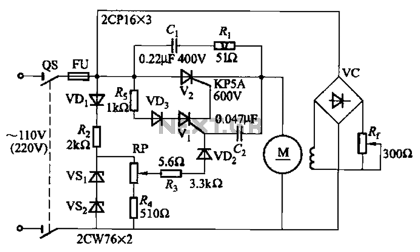
A 100W resistance-triggered motor control circuit designed for arc welding machines. It features an adjustment potentiometer (Rr) that can modify the DC motor excitation current. Additionally, a regulator (RP) is included to adjust the DC motor armature voltage, enabling...
Each keypad button generates a 5-bit binary code, which is transmitted by IC1 to the IR LEDs through diodes D1 and D2. The code is structured from six pulses interspersed with five gaps. The pulse position modulation (PPM) technique...
A four-channel data telemetry system featuring electronic circuits, schematics, hobby kits, custom electronics design, and a tutorials homepage. This platform offers a wealth of free, functional electronic circuits and a discussion forum with thousands of members to engage in...
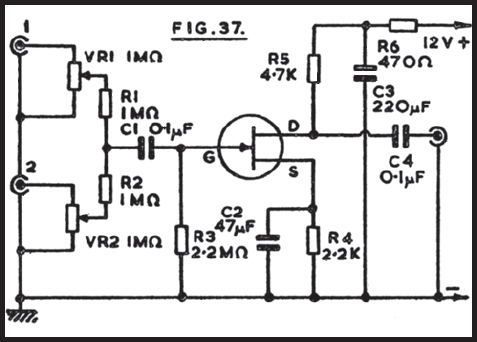
It is often convenient to fade in or out or mix the inputs from two audio sources at any desired level. The circuit depicted is suitable for this purpose. One input connects to socket 1, and the second to...
The CYB-P51 (Rev A) Prototyping Board is designed as a two-layer board without dedicated power and ground planes. All components, except for the premounted P-51, utilize through-hole technology for ease of probing and part replacement. The board features an...
The following circuit illustrates a Bass and Treble Controller Circuit. This circuit is constructed based on the classic Baxandall tone control circuitry. The Bass and Treble Controller Circuit is designed to adjust the low and high-frequency response of audio signals,...