
Multi-Tester Logic Probe Signal Tracer And Injector

The described circuit serves as a versatile test set designed for signal generation and audio output. The signal injector, represented by operational amplifiers U1A and U1B, is capable of producing two selectable frequencies: 10 kHz and 100 Hz. This selection is facilitated by switch SI, enabling the user to adapt the output frequency based on the testing requirements.
The logic probe, designated as U1C, is integrated into the circuit to provide visual feedback on the logic state of the signals being tested. This component is essential for diagnosing digital circuits, as it indicates high or low logic levels, thus assisting in troubleshooting.
The audio amplifier section includes operational amplifiers U1D, U1E, and U1F. This configuration is specifically designed to drive a piezo sounder element, which operates without an internal driver. By utilizing the piezoelectric effect, the sounder converts electrical signals into audible sound, functioning effectively as a piezoelectric speaker. The absence of an internal driver allows for greater flexibility in the circuit design, as it can be powered directly by the audio amplifier output, ensuring efficient sound production.
Overall, this circuit combines signal generation, logic testing, and audio output capabilities, making it a valuable tool in electronic diagnostics and testing applications. This circuit for a test set contains a signal injector (U1A/U1B) and associated com ponents, a logic probe (U1C) and an audio amplifier. SI selects either 10-kHz or 100-Hz output. U1D, U1E, and U1F form an audio amplifier that drives a piezo sounder element without an internal driver so that it functions as a piezoelectric speaker.
Related Circuits
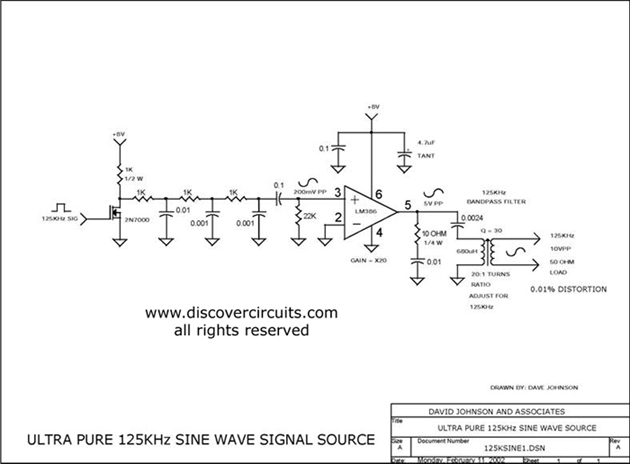
Ultra pure 125 kHz sine wave signal source. For certain RFID systems operating at 125 kHz, a very low distortion signal source is essential. The circuit presented here produces a 10-volt peak-to-peak signal. The ultra pure 125 kHz sine wave...
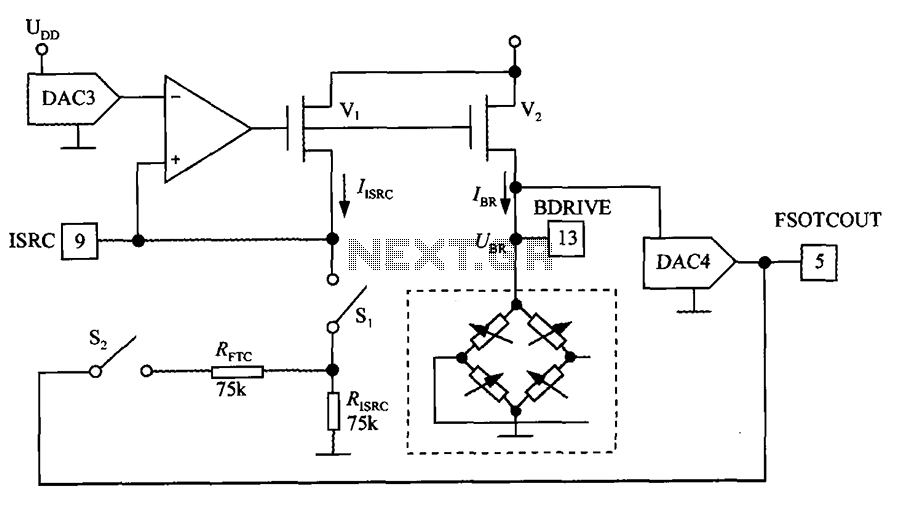
The excitation circuit for the digital pressure signal conditioner MAX1458 is illustrated. The output DAC3 is utilized to adjust the sensor excitation current (IBR), enabling full-scale fine calibration. The reference current (IISRC) is determined by the resistor RISRC and...
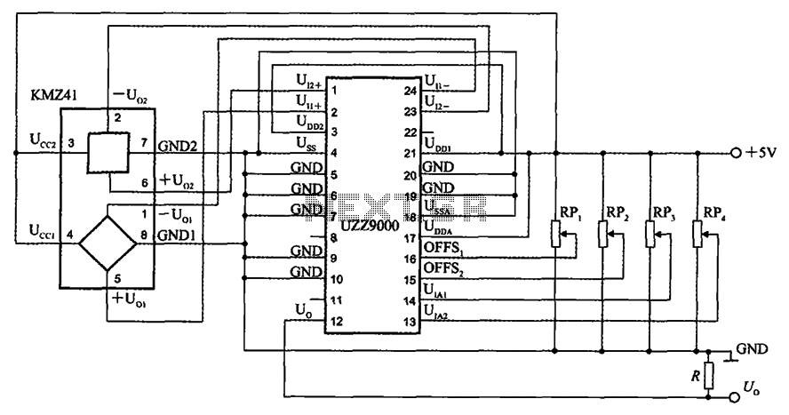
The UZZ9000 KMZ41 detection circuit is configured based on the voltage output type and angle. It operates with a +5V power supply. Potentiometers RP1 and RP2 are used for offset voltage adjustment, while potentiometers RP3 and RP4 are utilized...
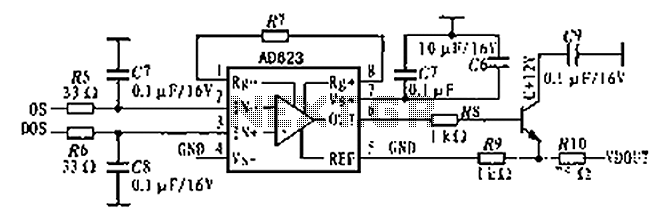
The AD623 is an integrated 3-way amplifier that can operate with either a single or dual supply. It features high common-mode rejection ratio (CMRR) and low voltage drift, along with programmable gain control via an external resistor. All components...
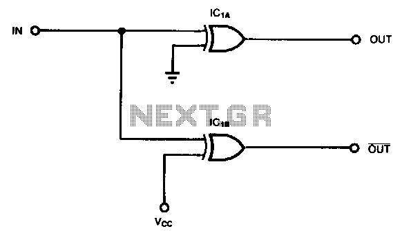
Some applications, such as driving three-state buffers for data multiplexers or for biphase clocks in high-speed systems, require complementary signals with minimal time skew and nearly simultaneous transitions. In this context, XOR gates serve as both inverting and non-inverting...
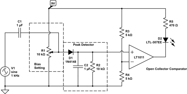
Control an LED with an audio signal; however, the output signal is only 150 mV peak-to-peak (with a 150 mV positive offset). It is understood that a higher voltage than 0.6 V is required to activate the transistor, leading...