
transistors Controlling LED with 300mV AC signal

To achieve the desired control of an LED based on an audio signal, a circuit can be designed that utilizes an operational amplifier (op-amp) to amplify the weak audio signal and drive a transistor, which in turn controls the LED. The circuit can be structured as follows:
1. **Input Stage**: The audio signal is fed into the non-inverting input of an op-amp. The op-amp should be configured in a non-inverting amplifier configuration to boost the signal. A suitable gain can be set using external resistors connected to the op-amp feedback loop. For instance, if a gain of 5 is desired, resistors R1 and R2 can be selected such that R2/R1 = 4.
2. **Offset Adjustment**: Since the original audio signal has a 150 mV positive offset, a DC biasing circuit may be required to ensure that the output of the op-amp is centered around the required voltage level to drive the transistor. This can be accomplished by adding a voltage divider connected to the op-amp input, which can set a reference voltage that aligns the output within the acceptable range for the transistor.
3. **Transistor Driver**: The output from the op-amp can be connected to the base of an NPN transistor. Ensure that the transistor is chosen based on its current and voltage ratings suitable for the LED load. A resistor may be placed in series with the base to limit the current flowing into the base of the transistor.
4. **LED Control**: The collector of the transistor connects to the LED, which is in turn connected to a suitable power supply. The emitter of the transistor should be grounded. When the op-amp output exceeds the base-emitter threshold voltage (approximately 0.7 V for silicon transistors), the transistor will turn on, allowing current to flow through the LED, illuminating it.
5. **Signal Strength Modulation**: If the goal is to control the intensity of the LED based on the audio signal's strength, the gain of the op-amp can be adjusted or a more sophisticated circuit with a pulse-width modulation (PWM) control can be implemented. This would involve using the op-amp output to modulate the duty cycle of a PWM signal that drives the transistor, allowing for finer control over the LED brightness based on the input audio signal amplitude.
This approach ensures that the LED responds appropriately to the audio signal, providing a visual indication of the signal's presence and strength. Proper consideration should be given to component selection and circuit layout to ensure reliable operation and minimize noise interference.Control a LED with audio signal, but the problem is, that output signal is only 150mVpp (with 150mVpp positive offset). In my understanding, it needs to be higher than 0. 6V to get the transistor running, therefore I am not sure what to use instead. Do I maybe need an opamp in the middle Any tips By "control an LED", do you meanthe LED should be on
when there is an audio signal, and off when there isn`t, or something more sophisticated such as intensity controlled by signal strength Anindo Ghosh May 11 `13 at 13:22 +1 to counter the drive-by down-vote. If there`s a need for a downvote, please consider leaving a comment explaining why, it helps new members improve their questions (and answers) for the future.
Anindo Ghosh May 11 `13 at 13:29 🔗 External reference
Related Circuits
This project uses a 3909 IC and a few other parts; power is 1.5 volts DC. The project employs the 3909 integrated circuit (IC), which is a versatile component commonly used in various electronic applications, particularly in timer and oscillator...

This design uses a smart card to enable a relay. A Nutchip recognizes its mating smart card among thousand similar ones, because you choose the code to be programmed in the card's memory. No specialized knowledge is necessary, as...

This circuit is a simple LED voltmeter designed to monitor the charge level of lead-acid or tubular batteries. The terminal voltage of the battery is displayed through four LED indicators. The nominal terminal voltage for a fully charged lead-acid...
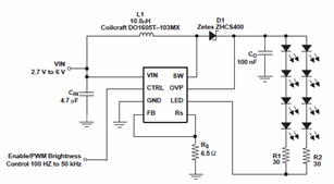
The schematic diagrams for the TPS61042 current LED driver illustrate its capability to power eight LEDs with an efficiency of 81% at 3.6V and 18.6mA. The TPS61042 is commonly utilized in applications such as white LED supply for backlight...
The LED power Meter is a simple RF detector using diodes to charge a capacitor. The voltage developed across the capacitor is indicated by a multimeter set to a low voltage range. The circuit is soldered together without the...
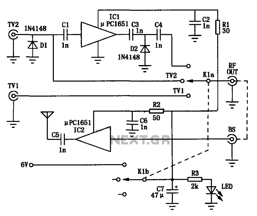
Amplification is utilized to convert video output signals from various devices, such as VCRs and DVD players, which often require amplification of weak output signals. Additionally, it can transmit radio frequency signals over a radius of approximately 7 meters,...